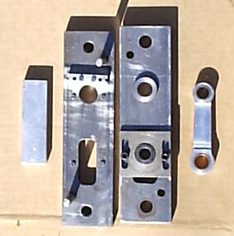
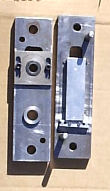
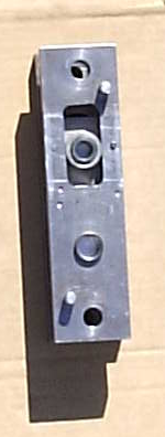
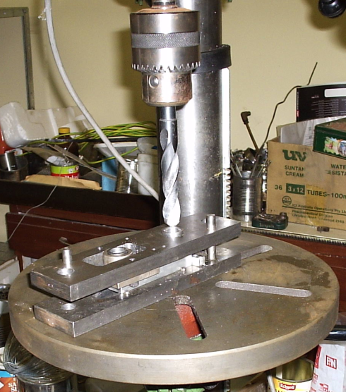
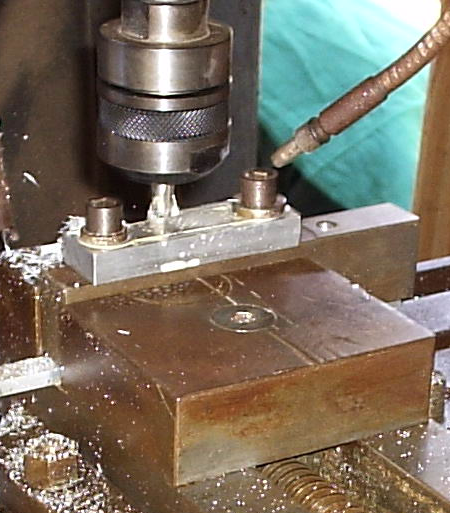
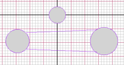
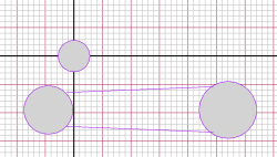
Having now drilled the bearing holes we can bolt the Conrod blank to a
holding
fixture and proceed to mill away the side clearances on
both sides using a face mill.
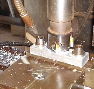
Fig-4 Starting the
Clearance cut of the
conrod.
|
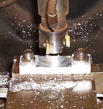
Fig-5 End of the Clearance cut.
|
The clearance operation is done
in two passes
( Top & Bottom ) using the same G-code file below,
Notice the file is made up of
four basic sections,
- Preamble containing set up instructions and commands
- Subroutine Section
- Main part of the program
- Cleanup, storage of tools and moving the machine to the
start position ready for the next part.
Conrod
Clearance Cut G-code File Listing of the file, 'CONROD_CLEAR.ANC'
(
THIS FILE MACHINES SIDE CLEARANCE INTO THE CONROD
( ORIGIN IS OVER THE SMALL END WHICH
IS TO THE LEFT.
( USE 40MM CUTTER AT 1200 RPM.
( SET TO START POSITION INITIALLY
USING SUBROUTINE-1.
( USE SUBROUTINE-2 TO MILL THE
CLEARANCE FOR ONE SIDE, THEN TURN OVER
AND CUT
( THE OTHER SIDE.
( USE 40MM CUTTER AT 1200 RPM.
( Blank is 83 * 20 * 12 thick
Alluminium
(================================
Setup commands
====================================
G90
( Absolute co-ordinates used.
G71
( Set
to Metric system (millimeters) measurement units.
G94
( Set
Feedrate to units per minute.
F100
( Feedrate
is 100 mm per minute.
T#1 40.0 0 ( Set up 40mm cutting Tool
and load it.
(================================
Subroutine Section
===================================
G57R1 ( During Setup, locate cutter
over little end & then move to
start position 0,0
G0X20
G0Y40
G58
(
G57R2
( Mill side clearance for one
side
G1Y-40 ( Cut
along the 'Y'axis 40 milli metres
G1X4.5
( Cut along the 'X'axis 4 & 1/2
milli metres
G1Y0
( Cut back to Y = 0.0
G0X0
( Fast travel back to
starting point.
G58
(=========================== START
MAIN PROGRAM HERE
================================
( G59R1C1 ( setup
routine, comment out once setup
done! Locate Spindle directly over the left bearing to begin Setup.
G59R2C1 ( Mill side clearance for one
side, comment out during setup
M2
Stage-3:
Machining the
Outside of the Conrod blank.
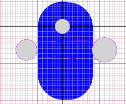
Shown below is the cuting of the
outside shape
of the rod using a
slot drill.
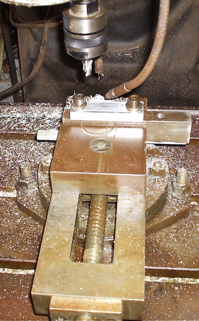
Fig-6 Starting to cut
the outside of the
conrod.
|
Fig-7 Conrod Outside cut
Underway! |
Notice again that the file is made up of the four basic sections,
- Preamble containing set up instructions and commands
- Subroutine Section
- Main part of the program
- Cleanup, storage of tools and moving the machine to the
start position ready for the next part.
Outside
Shape G-code File Listing of the file, 'CONROD_OUTSIDE.ANC'
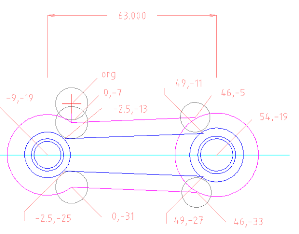
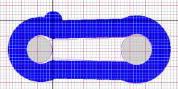
( THIS FILE MACHINES THE OUTSIDE OF THE CONROD AT 63 MM BETWEEN CENTERS.
( ORIGIN IS OVER THE SMALL END WHICH IS TO THE LEFT.
( USE 12MM CUTTER AT 1200 RPM.
( SET TO START POSITION INITIALLY USING SUBROUTINE-1.
( USE SUBROUTINE-2 TO MILL THE OUTSIDE.
( Blank is 83 * 20 * 12 thick Alluminium
(================================ Setup commands
====================================
G90 ( Absolute co-ordinates used
G71 ( Set to Metric system (millimeters) measurement units
G94 ( Set Feedrate to units per minute.
F60 ( Feedrate is 60 mm per minute
T#1 12.0 0 ( Set up 12mm cutting Tool and load it
(================================ Subroutine Section
===================================
G57R1 ( During Setup, locate cutter over little end & then move to
start position 0,0
G0X9
G0Y19
G58
(
G57R2 ( Cut around to create outside shape
G1Y-6
G1X46Y-5
G2X8.2Y14I8.2J-14
G1X46Y-33
G1X0Y-32
G2X-8.3Y-13I-8.3J13
G58
(============================= START MAIN PROGRAM HERE
==============================
(G59R1C1 ( Setup routine
G59R2C1 ( Cut around to create outside shape
G0Y0 ( Home tool to start position
G0X0
M2
