side4linux, a simple integrated development
environment!
ANCA
Demo-2 -- Introduction to Bdesign3d the three
dimensional design program.
( Updated: May 4, 2008 )
Coders, please refer to the Bdesign3d Specification Level D2 available
in the 'Specification' folder of the Bdesign3d
Project.
Purpose: To introduce
3d modeling suitable for use in a metals manufacturing environment.
Requirements:
Make sure that the latest
help packages are installed.
Pre-Requisites:
Do Demo-1
first.
Notes: This
file contains some of the programming 'wish list' to be
used by the programming team to create the 3d modeling tool
'Bdesign3d'. Please have a quick read before using the Tool so that you
can grasp some understanding over what goes on behind the program's
HMI ( human machine interface ). Do not worry if you cannot grasp all
that is mentioned here as actual instructions on
how to use the Tool will start in Demo-6. Take the advice that this is
a work in an early state of development so follow each feature's
introduction in the Demo's to come as announcement of their inclusion
into the feature list! The Demo is presented as a simple two bladed
airplane propeller and will have images of the working program included
as it develops toward public release.
Overview of Bdesign3d:
- Part manufacture and placement
- Object Interface
- Animations Interface -- Object Side
- Actions Interface
- Modal Commands
- Animation Engine
- Moving from Design to Manufacture
Notes on special type usage,
'SOME-ITEM'
= command or word of special significance
'SOME-ITEM'
= command or word of special significance that has been introduced
which we would like you to remember.
command x,y,z =
separating commas means all items are required, e.g. command 3 5 6
command x/y/z =
separating slashes means items are optional, e.g. command XY
command x^y^z =
separating up arrows means items that are exclusive of each other, e.g.
command X or command Y etc. etc.
1 Part manufacture and placement
CAM
packages differ from CAD in that apart from just computer aided design
there should also be tools provided to
turn out dies or molds of any part automatically along with the
possibility of creating 'tool path'
files for laser cutting, welding etc. Other advancements would include
torsional, strain and fatigue testing along with total constructed
weight and manufacturing cost estimation. Therefore
the purpose of using a three dimensional CAM package is the graphical
depiction of an object to be manufactured along with the tools to make
that happen.
A design product 'object' (
called the object 'ALL' in
this program ) is made up
of an 'assembly' various 'parts'. These part 'objects' are
built up of smaller 'geometrical
shape' objects in an 'Object
Factory' around the 'origin'
of 0:0:0 or X=0,Y=0,Z=0. Once a 'part' object
has been
created by the graphic designer in the 'Object Factory' it would then
be moved and rotated into the correct position using a process
called 'assembly'. This
collection of 'part' objects creates the product object 'ALL' also known as the 'model' because it is a small sized
virtual replica of the completed product.
Following this 'object orientated'
process the designer will 'animate'
the final assembly of the
object 'ALL' to view the possibility of any jamming or interference of
one part with another. The
designer could then proceed to make a small
sized 'model' by 'RPP' or
Rapid Prototype Printing ( the building
up of parts on a 3D replication machine, one layer at a time ).
The 'RPP' approach is often used
because a design such as a motor car must be visually appealing to
prospective
purchasers as well as being mechanically functional. The approval
process is enhanced because 'RPP'
allows the designer to assemble the 'model' so that the complete design
may be viewed 'with the hands'.
By using an 'object orientated'
approach any part may be modified individually and placed back into the
design. Options are provided to cause other parts to
'self modify' or 'morph' so
that the modified part may automatically fit back into the design. I
say optional because of the cost of
morphing must include provision for making new dies or molds. Another
option would be to morph the redesigned component to fit with
existing parts.
Object
orientated
CAM design makes it easy to re-design things so that design and
development may continue on for the life of the product. This makes it
essential that standard CAD design procedures are enhanced by a built
in design language which would include 'wizards'
for creating standard parts such as ball race bearings, nuts and
bolts etc. This design language would be textual and it would need to
be 'embedded' within each
'part' object, making it much easier to understand the construction of
a part
at a later time.
Summary:
- Part 'objects'
are designed out of
'geometrical shape'
'objects' in an 'Object Factory'
around the 'origin' of 0:0:0
- Part
'objects' are then assembled into the object 'ALL' by a process of movement and
rotation called 'assembly'.
- The
object 'ALL' is known as the 'model'
because
it is a small sized virtual replica of the complete assembly.
- The
designer should 'animate'
the final assembly of the object 'ALL' to view the possibility of any
interference of one part with another.
- 'RPP'
allows the designer to assemble the 'model' so that the complete design
may be viewed 'with the hands'.
- By
using an 'object orientated'
approach any part may be modified individually and placed back into the
design.
- Parts
can be 'morphed' so that
a modified part may
automatically fit back into the design.
- A built
in design language would include 'wizards'
for creating standard object 'parts' such as ball race bearings, nuts
and bolts etc.
- The
design language would be textual and 'embedded'
within each part 'object'.
2 Object Interface
The 3d design is stored in 'Bdesign3d' as an 'OBJECT
TREE'. All Objects are children of the Object 'ALL' which is the
complete 3d design. The first level below 'ALL' is called the 'BASE
LEVEL' and on opening the program the 'OBJECT EXPLORER NOTEBOOK' will show
the object 'ALL' and it's children the 'BASE
OBJECTS'. There must be at least one 'Base Object' left in the
'Object Tree', even if it is empty. Base
Objects can have their own children objects so you will find an
'expander-arrow'
to click on to see them. Bdesign3d has three operational 'MODES' they
are 'INTERACTIVE' mode,
'ANIMATION' mode and 'RE-DRAW' mode. Let us take a look
at what happens
when Bdesign3d enters 'INTERACTIVE' mode on start-up. On opening a 'bd3' file the program sets up the
'object tree' for object 'ALL' and displays it in the 'Object Explorer
Notebook' as in figure-1 below where our test sample file is
loaded.
The file describes a two bladed airplane propeller project with three
'base objects' ( 'RightBlade'
with it's 'child' object
'BalanceWeight',
'LeftBlade' and 'PropHub' ) as children of object 'ALL',
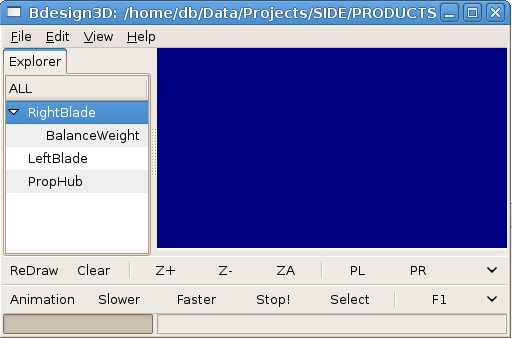 Fig-1 Bdesign3D showing Object Tree
structure for object 'ALL'
Notice in figure-1 that 'ALL' is in the 'Explorer Notebook' tab and 'base objects' always
start in the first column ( as 'children' of 'ALL' ).
Notice that 'RightBlade' has an 'expander
arrow', left click on the arrow to see the object's 'children',
Also notice that each 'child'
of an object starts one column further to
the right.
- Try moving the objects around by holding down the left
mouse button and
dragging an object onto another and then releasing the button.
- You can make one object the 'child object' of another
object.
- Notice that when you move an object you also move all of
it's
'children' objects.
- Try making the object 'RightBlade' the 'child' of
object 'LeftBlade' as in figure-2 below, then 'drag' them back to
the 'state' shown in figure-1
above.
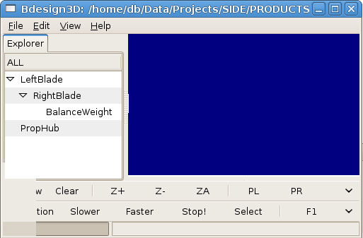 Fig-2 Bdesign3D, moving 'RightBlade'
to be 'child' of 'LeftBlade.
- Try 'inserting' a
child object ( it will be called 'NEWobject' by default, right click on
'BalanceWeight' and left
click on 'Insert'
in the 'popup menu' as in
figure-3 below,
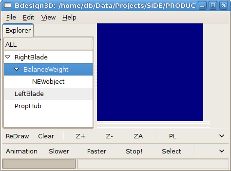 Fig-3 Bdesgn3d, Inserting a 'child'
object into the Object Tree.
- Try 'deleting' an
object, right click on 'NEWobject' and
left click on 'Delete' in the
'popup menu'.
- Note: You can 'Promote'
a 'Child Object' to be a 'Base Object' by dragging it to the bottom of
the Object Tree.
- Try to 'Demote' a
'Base Object' to be a 'Child Object' by dragging it to be a 'child' of
another object.
- Try adding a new 'Base Object', right click on any object
and left click on 'New' in
the 'popup menu' as in
figure-4 below,
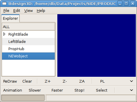 Fig-4 Adding a New 'Base Object' into
the Object Tree.
- Note that new 'Base Objects' are inserted into the bottom
of the Object Tree.
- You can then drag 'objects' wherever you wish, 'Demoting'
or 'Promoting' them as you go.
- Try adding another 'New
Object', it fails because 'NEWobject' is already in the Object
Tree, we will need to 'rename'
'NEWobject' before adding another.
- Right click on 'NEWobject' and left click on 'Edit' in the
'popup menu' to bring up the 'Object
Inspector' window as in figure-5 below,
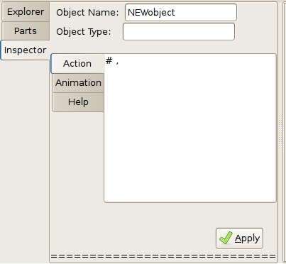 Fig-5 Bdesign3D Object Inspector
- Note there is an 'Action-List' and an 'Animation List',
and the 'Object Name' entry shows 'NEWobject'.
- Change the object name
from 'NEWobject' to 'Propeller', click on 'Apply' and then 'Close'.
- Notice that the object has changed from 'NEWobject' to 'Propeller' as in figure-6
below,
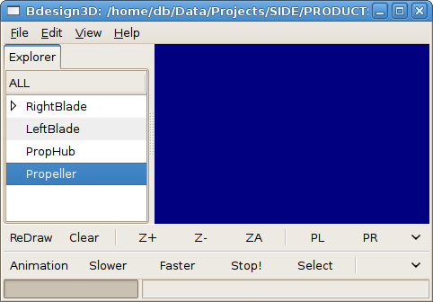 Fig-6 Rename an 'Object Tree'
'object'.
- Now 'drag' the
'objects' around until they are all 'children' of 'Propeller', as in figure-7 below,
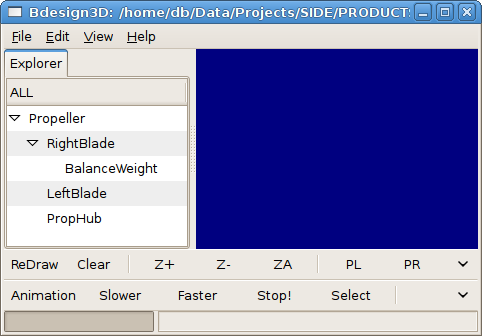 Fig-7 Re-ordering to make object
'Propeller' parent of other objects.
- Note: By
adding 'Base Objects' and making existing 'objects' the 'children' of
the new 'object', you can make very large 'models'.
- For example you could add the object 'engine' and make 'propeller' a
'child' and you could add 'airframe'
and make 'engine' a 'child' and so on....
- Try deleting all of the objects in the 'Object Tree', by
deleting 'Propeller' ( CAREFUL 'Delete' deletes an
'object' and ALL
of it's 'children' ).
- You will find that at least one 'Base Object' must remain
as a child of 'ALL', even if it is just a 'NEWobject'.
- If you delete objects, one object at a time, you will get
the error message ( or something similar ) shown in figure-8 below once
you reach the last object in the 'Object Tree',
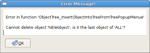 Fig-8 Bdesign3D Error Window with an
error
on trying to delete the Last Object.
2.1 Objects
Well, what is an 'Object' then?
- An 'object' is an item, for example an automobile (
motor car ) is an object.
- A car is
made up of smaller objects ( it's 'children'
or 'child objects' ) such as
an engine, gearbox, wheels, headlights etc.
- These
'child-objects' are said to be 'members'
of the 'parent-object'.
- These
'child objects' are ( more than likely ) made up of a collection of
smaller 'child' objects', for example a gearbox would contain gears,
shifting mechanism, housing, bearings etc.
- Objects
have 'Properties', for example
the fuel tank would have the 'property'
of 'fuel-level-remaining'.
- Object
properties are not directly 'visible'
from other objects and cannot be directly 'accessed' by another object.
- Objects
also have 'Methods', for
example the fuel tank would have a 'method'
to read the fuel level remaining, if asked.
- Objects 'call' another object's methods to 'set' or 'get' a 'property' or initiate an 'action'
by the called object.
For example, in the case of a car driver increasing the vehicle's speed
by pressing down on the accelerator peddle, the 'method, of 'setRPM' of the engine object [
engine.setRPM(newRPM) ] would be 'called' by the accelerator
peddle object of the car object. In time the gearbox object may respond
to it's 'speed-changed' 'callback
signal' and react by calling the speedometer object's
method 'speedo.setCurrentSpeed(newSpeed)'.
- 'Actions' taken by objects may be 'immediate' ( take place as soon as
they are 'called' ) or be 'event
driven' ( when something specific happens the object will 'emit' a 'callback-signal' that calls a
specific 'callback-handler'
function.
- An
object's 'methods' are made 'public' by 'declaring' them in some way.
- If an
'object' is removed then the 'methods' it has 'declared' must also be removed or a
'dummy' set of objects/methods put in place to prevent 'error handlers' becoming active
when another object 'calls' a
non-existent object's method/s.
- Objects
must have 'unique names' to
prevent situations where the wrong object is called.
- In
computer programing an object's methods become distinctive by using the
addressing technique of 'object_name <> object_method_name' as in
'starterMotor.turnCrankshaft'.
- An
object/method/property name should be descriptive, that is anyone can
clearly understand what the object is, what a method does and what sort
of data a property represents.
- An object
'inherits'
from it's 'child' objects their 'properties' and 'methods', this
allows for some very useful ideas,
- an
object such as a 'fuel tank' that holds liquid fuel is very different
from a tank holding hydrogen gas but the 'method'
to read them can be made to look the same to the calling object. This
means that a car's 'fuel-gauge' 'object'
need not know the make-up or internal workings of it's 'child object' 'fuel-tank' to
understand how
much fuel remains.
- objects
can be made to be 're-usable'
e.g. the same fuel tank may be used on different cars or bigger fuel
tanks could be used depending on whether the car is for town or country
use. This is
possible because 'methods' 'hide'
any differences that you do not want other 'objects' to 'see'.
- 'objects'
will not interfere with the operation of 'un-associated' 'objects'.
- using
objects allows for 'compartmentalisation'.
This allows big projects to be handled easily with many workers
building in functionality through an agreed interface ( 'methods' ).
- customers
will always be able to use a product because while the internal
workings may be different, the controls can remain similar to other
familiar products.
- objects
can be 're-used', for example
the program 'Bdesign3D' uses many sections of code borrowed from the
'side4linux' IDE saving time, money and effort!
- object
based projects can be made flexible, it is no longer necessary to be
exactly precise first up. Build the top level object first and add,
subtract or
modify child objects as progress is made.
- object
based products
are never 'finished'! You can keep making alterations to repair bugs
or to upgrade as required, ...... forever.
- object
based projects can be customer friendly because customers need not be
engineers to be involved in product development. Customers often know
what they
want and technical detail can be 'hidden'
at a lower object level ( this is called 'abstraction').
- because
objects can be re-used it becomes possible to build up a library of
test functions to iron out bugs, this makes the object more robust.
In Bdesign3D a
design is built up either from the top ( 'top down methodology' ) or from the
bottom ( 'bottom up methodology' ) or both. This design paradigm
creates a 'model' of the real
thing which we then call the 'set'
of 'ALL' ( notice the use of
the 'set' terminology, e.g. to
drill a hole one could use an 'invisible' cylinder 'object' and 'subtract' it from another 'object' ). The
'children
objects' objects of the 'set of ALL'
contain all that is needed in the way of methods and properties
to be drawn on screen. This is possible because each 'object' may
contain
an 'Action-List' to call
'methods' to do something or alter a 'property'. Each object may also
contain an 'Animation List' to
allow objects to be moved around on screen either on their own or
linked to other objects. Some Object types are simple e.g. the
object 'POINT' while most objects are complex and made up of many other
objects. Objects are kept in an 'OBJECT
TREE' and during the 'RE-DRAW'
phase the parsing mechanism firstly
travels down to the bottom of the tree branch of the first object
drawing the object's 'children
objects'. Once the base level object is fully
drawn the parser will move onto the next base level object until the
end of the object tree is reached and the object 'ALL' has been
completely drawn. After
the 'RE-DRAW' mode has ended the program returns
to 'INTERACTIVE'
mode. During object creation the program ensures that only 'unique object names' are entered
into the tree of object 'ALL'. Notice in
figure-2 above that we have used both upper and lower case letters for
object names ( we could have used numbers and the 'under-bar' symbol as
well ), this prevents any
clash with reserved words which only use upper case letters and the
'under-bar' symbol as in 'RESERVED_WORD'.
In Bdesign3d, 'objects' can be of three 'class'
types,
- OBJECT_ENTRY ( the
object names you see in the Object Tree, such as 'RightBlade' or
'PropHub' etc.
- COBJECT_ENTRY (
the
object names you see in the Object Tree, such as '$RightBlade' or
'$PropHub' etc. represent a 'Compounded' group of 'objects'. These
object groups are created by an 'Object-Wizard'
and cannot be edited in the normal 'Object-Inspector'
window, they must be re-submitted to the relevant 'Object-Wizard-Inspector' window for
editing.
- GEO
these
are geometrical objects ( e.g. 'LINE'
or 'CIRCLE' ) and appear only
within an 'OBJECT_ENTRY's, Action
List',
however 'POINT' objects
can be 'referenced' from an
external object's
'Action-List' by pre-pending the external object's reference name with
'@'
and appending the external point reference
name preceeded by a 'dot',
- GEO Point example: GEO,POINT,@RightBlade.P1,@RightBlade.P2
Summary:
- Object names must not
contain punctuation marks ( such as full stop or comma ) only upper and
lower case letters, numbers and the 'underbar' symbol.
- Object names must start with an 'alpha' character, not a
number or an underscore.
- Object names starting with the dollar mark '$' are
'Compound Object' entries handled by the program's 'object wizards' and
cannot be entered manually.
- Object names prefixed with an 'at' character '@' are references to
external
geometry POINT objects such as '@blade.p1', ( go to the 'Action-List'
of object 'blade' for the geometry 'POINT' object 'p1' and read the XYZ
co-ordinate values found there ).
- Object referencing using '@' is only allowed from within
an OBJECT_ENTRY's 'Action' or 'ANIMATION' List.
- OBJECT_ENTRY names must be unique within the object 'ALL'
and should be made up of upper/lower case alpha letters and/or numbers
and/or the 'underscore' character.
- GEO 'POINT' names are required to be unique only
within the OBJECT_ENTRY where they are declared and are referenced from
outside using the 'at' '@' and 'dot' '.' symbols.
- All object names must be in 7 bit ASCII format, UTF8 or
'wide' encodings are not recommended.
- examples
follow...
Object
Name
|
Comment
|
RightBlade_3
|
OK.
|
RightBlade:3
|
Invalid use of 'colon'
':' between 'RightBlade' and '3'.
|
| RightBlade-3 |
Invalid use of 'dash' '-'
between 'RightBlade' and '3'. |
RIGHT_BLADE
|
Works but not
recommended, use
more than uppercase alone.
|
Right3Blade
|
OK.
|
Right
Blade
|
Invalid use of space ' '
,
spaces are
not allowed anywhere in user input except for comment lines.
|
3RightBlade
|
Invalid, object names
must start with an 'alpha' character.
|
| #RightBlade |
Invalid use of hash '#'
character reserved as start of a 'comment' line.
|
@blade.p3
|
OK, as a reference value.
It says "read object 'blade'
to obtain the 'POINT' value of 'p3'
".
|
@bladep3
|
Invalid, must have a
decimal point to separate OBJECT_ENTRY from GEO ( @blade.p3 )
|
2.1.1 Object Entry
Objects
are 'declared' into the
'Object File's 'Object Tree' as,
'OBJECT_LIST_START, '
'OBJECT_ENTRY,objectName, '
.... various 'Properties' added to
the object e.g. an 'Action List' or an 'Animation List'.
'OBJECT_ENTRY_END,objectName, '
'OBJECT_LIST_END,
Note:
'objects' can also be affected by 'modal'
commands such as 'Show' or 'Hide', see 'Modal Commands' further down
for more information.
2.1.2 Geometric Object Inclusions
'GEO's are
'declared' into the 'Action'
list of an object, this is the graphical representation part of the
Bdesign3d modeling interface with a geometric include command such as,
ACTION_LIST_START,
# a line from point 'Start' to point 'End' of 10.0 along the X axis,
GEO,POINT,PointStart,50.0,8.4,3.2,
GEO,POINT,PointEnd,60.0,8.4,3.2,
GEO,LINE,PointStart,PointEnd,
END_ACTION_LIST,
'GEO'
names must be unique within the 'OBJECT_ENTRY's 'Action' list and follow the
specified object naming criteria outlined above.
'GEO' 'POINTS' must
be declared in the 'Action-List'
before they are locally referenced.
'GEO's can be 'referenced' by the 'Action-List' of
another object using the '@' 'reference
prefix' however the 'object' to be referenced must have
been 'declared'
previously in the 'OBJECT_ENTRY' list, look at the following
two objects,
OBJECT_ENTRY,RightLine,0,
#,
ACTION_LIST_START,
OBJECT_MATERIAL,STEEL ,
GEO,POINT,p1,50.0,8.4,3.2,
GEO,POINT,p2,60.0,8.4,3.2,
GEO,LINE,p1,p2,
END_OBJECT_ENTRY,RightLine,
#,
#,
#,
OBJECT_ENTRY,LeftLine,1,
#,
ACTION_LIST_START,
OBJECT_MATERIAL,STEEL,
# ======== the next line will reference another object's points,
GEO,LINE,@RightLine.p1,@RightLine.p2,
<-------------<< External
Referencing
# mirror across the 'Y' axis,
MIRROR_OBJECT,Y,
END_ACTION_LIST,
END_OBJECT_ENTRY,LeftLine,
- Object
'RightLine' was declared previous to Object 'LeftLine'.
- You can see that
object 'LeftLine' is 'referencing'
some of object 'RightLine's 'POINT'
'GEO's.
- This means that any alteration to the value of
'RightLine's 'referenced'
'POINT's will dynamically affect 'LeftLine'.
- Notice that all lines are terminated with a comma and a
space,
even 'comment' lines. Comment lines always start with the 'hash and
comma' '#,'
characters in the first character position of the line followed by some
text then terminated in the usual way of 'comma and space', E.G. '# this is a comment line, ' or a
blank comment line '#, '
- Note: If you are looking to 'reference' all of the points
of an
object it may be a lot quicker to 'copy' it, refer to the 'Action-List'
commands for details.
GEO's
|
Description |
Active
|
|
|
|
ARC,point_objects,
|
-- a radial curved line segment
(startvertex,center_vertex,end_vertex). |
|
CIRCLE,point_objects,
|
-- a closed radial curved line
segment (center_vertex,radius_vertex).
|
|
CLINE,point_objects,
|
-- a construction line
segment(start_vertex,end_vertex). ( used to help build other GEOS )
|
N |
| COMPLEX (complex extrusion) E |
-- start POLYGON, end POLYGON, start vertex, end vertex,
No. of
segments, spiral_diameter, pitch, rotation_point, twist,
dragline1,
dragline2, dragline3, dragline4, 'OPTIONAL-ITEMS', END.
|
N
|
DIEMOLDC,point_objects,
|
-- circular
multi part die block, ( center vertex,radius vertex ) as the set
subtraction of objects. |
N
|
DIEMOLDR,point_objects,
|
-- rectangular multi part
die block, ( corner1,corner2 ), as the
set subtraction of objects. |
N
|
| DIMANGLE,point_objects, |
-- a dynamic angular measurement at angle A (
start_vertex,center_vertex,end_vertex with text offset vertex ). |
N
|
| DIMENSION,point_objects,
|
-- a dynamic linear measurement at ( start_vertex,end_vertex with text offset
vertex ). |
N
|
| DISC_HOLLOW,point_objects, |
-- flat circular disc
with center hole ( center_vertex,radius_vertex,hole_radius_vertex
). |
N
|
| DISC_SOLID,point_objects, |
-- flat circular disc
without center hole ( center_vertex,radius_vertex
). |
N
|
EXTRUSION ,sPy,ePy,sPt,ePt,N,S,D,T,E,
|
-- startPOLYGON, endPOLYGON, start_vertex, end_vertex, No. of segments, sweep, droop, twist,
'OPTIONAL-ITEMS', END. |
N
|
| LINE,point_objects,
|
-- a line
segment(start_vertex,end_vertex). |
|
| LOOP,point_objects, |
-- a line loop of line
segments where the last segment joins the first segment.
|
N
|
| LOOPS,point_objects, |
-- a line loop of splined
segments where the last segment joins the first segment. |
N
|
POINT,name,X,Y,Z,
|
-- a vertex definition in
floating point numerical format. |
N
|
POLYGON,point_objects,IVAL,
|
-- a regular polygon of
connected POINTS of size P1 + P2 and IVAL number of sides. |
|
| POLYHEDRON,point_objects,IVAL, |
-- a regular polyhedron of
connected POINTS of size P1 + P2 and IVAL number of sides.
|
N
|
| RECTANGLE,point_objects, |
-- a rectangle of Length
( P1 )
by Breadth ( P2 ) point_objects. |
N
|
| SPHERE,point_objects, |
-- s sphere ( center
vertex, radius_vertex ). |
|
| SPLINE,point_objects, |
-- a spline
curve ( start_vertex,....,vertex_n ) with control points. |
N
|
SWEEP
spline_object,SA,EA,So^Si^N
|
-- a sweep of line (
start_vertex to end_vertex ). |
N
|
| SWEEPL
loop_object |
-- a sweep of a line
loop ( start_vertex to end_vertex ). |
N
|
| SWEEPLS
loop_object |
-- a sweep of a spline
loop from Start Angle to End Angle. |
N
|
SWEEPOLYGON,polygon_object,point_objects,
|
-- a circular extrusion
of a polygon, vertex-1 is the center, vertex-2 is the diameter,
vertex_3 is the orientation. |
N
|
| SWEEPSL
spline_object,SA,EA,So^Si^N |
--
a sweep of a splined
line from Start Angle to End Angle. |
N
|
TEXT,text_string,S,point_objects,
|
-- a block of text of Size
starting from start_vertex and extending in the direction of
end_vertex plus size vertex.
|
N
|
TRI,point_objects,
|
-- a series of 3 points
that describe an irregular triangular surface. |
|
2.1.2.1 EXTRUSION and COMPLEX 'OPTIONAL-ITEMS'
Extrusions can have a number of 'OPTIONAL' items added
after the 'MANDATORY' items
and before 'END'
as follows,
|
Type |
Description |
Active |
|
|
|
| 'WITH-RIBS' poly_object
|
-- Wing ribs
instead
of segment wire frame. Wing ribs can have
access holes for
pipes
and
tanks added as required by attaching 'children'
objects. |
N
|
| 'WITH-BULKHEADS' poly_object
|
-- Bulkheads instead
of segment wire frame bulkheads
can have door and other objects
added
as required by attaching 'children' objects. The
poly_object is the cross section
of the bulkhead from center.
|
N
|
| 'WITH-FORMERS'
poly_object
thickness |
-- Formers instead of segment
wire frame formers can have holes added
as required
via
the poly_object. |
N
|
| 'WITH-STRINGERS' poly_object R^P |
-- Stringers instead
of segment wires, the shape of
stringers is determined by
the
poly_object and remain the same size if the 'P'
flag is set or can reduce in
proportion
to the extrusion if the R flag is set |
N
|
| 'WITH-PATH' spline_object |
-- If the end point
of an extrusion is equal to the start point then this option must be
used,
it replaces a straight line with a B-spline curved line object to
follow.
|
N
|
| 'WITH-OUTER-SURFACE' |
-- Adds an outer SURFACE to the wire
frame extrusion. |
N
|
'WITH-START-SURFACE'
|
-- Adds a start SURFACE to the wire
frame extrusion.
|
N
|
| 'WITH-END-SURFACE' |
-- Adds an end
SURFACE to the wire frame extrusion. |
N
|
- The use of wing ribs allows
extrusions to describe a built up airplane wing structure.
- The use
of bulkheads allows extrusions to describe a ship
hull.
- The use
of formers allows extrusions to describe an
airplane fuselage.
- The use
of stringers allows extrusions to describe a
framework either open or covered.
Note: 'DRAG-LINE' is a line of points. Drag lines are used to hold
editing points of the extrusion allowing the extrusion to be manually
changed in cross-section, twist etc.
2.1.3
Pre-Built 3D Objects ( all pre-built objects end with 'V,V' which is 'start_Vertex,endVertex'. ) [ this is a wish list,
your wish not here? THEN ASK NICELY! ]
|
Type |
Description |
Active |
|
|
|
| BOLT_CAPHEAD,S,V,V, |
-- Describes a Standard
cap headed screw.
|
N
|
| BEARING_BALLRACE,S,V,V, |
-- Describes a
Standard radial
ball race bearing.
|
N
|
BEARING_COLLAR,O,I,N,C,T,V,V,
|
-- Describes a bronze
bearing with thrust collar of Outside diameter,Inside diameter,Collar
diameter,collarThickness. |
N
|
BEARING_PLAIN,O,I,W,N,V,V,
|
-- Describes a plain bush
type bronze bearing of Outside
diameter,Inside diameter,Width. |
N
|
BEARING_ROLLER,S,V,V,
|
-- Describes a
Standard
roller
bearing. |
N
|
CENTER_DRILL_POINT,S,,V,V,
|
-- Describes a center
drill hole of Standard
size ( 0 -> 6 ).
|
N
|
| GEAR_SPUR
N,I^M,P,B,F,V,V, |
-- Describes a Spur Gear
type of N teeth,Imperial or Metric ( 'dp' or
'module' ), Pitch, Back axis_vertex, Front axis_vertex. |
N
|
HOLE_CIRCULAR,D,V,V,
|
-- Describes a circular
hole of Diameter.
|
N
|
HOLE_FLAT_SIDED,S,V,V,
|
-- Describes a flat sided
hole with number of Sides. |
N
|
| HOLE_SPLINED,S,V,V, |
-- Describes a Standard splined hole. |
N
|
NUT_FASTENER,S,V,V,
|
-- Describes a
Standard hexagonal
threaded fastener nut.
|
N
|
SPLINE_LENGTH,S,V,V,
|
-- Describes a Standard splined length.
|
N
|
THREADED_LENGTH,T,V,V,
|
-- Describes a length of
metric threaded rod of Thread
size.
|
N
|
2.2 Object Properties
Property
Name
|
Hue
|
Description |
ALLUMINIUM
|
|
-- Silvery color non
transparent material with high reflectivity. |
BOLTSTEEL
|
|
-- Silvery/Purple
color non transparent material with high reflectivity. |
TITANIUM
|
|
-- Silvery/Blue
color non transparent material with high reflectivity. |
STEEL
|
|
-- Grey/Blue
color non transparent material with high reflectivity. |
CARBON
|
|
-- Dark
Grey color non transparent material with medium
reflectivity. |
COPPER
|
|
--
Reddish color non transparent material with high
reflectivity. |
BRASS
|
|
-- Yellow/Brown
color non transparent material with high reflectivity. |
BRONZE
|
|
--
Reddish/Brown color non transparent material with high
reflectivity. |
GLASS
|
|
-- Clear
color with light blue tinge transparent material with some reflectivity. |
PERSPEX
|
|
-- Clear
color with sky blue tinge transparent material
with some reflectivity. |
NOTHING
|
|
-- Background color used
for
set
subtraction, e.g. for 'drilling' a hole. |
FLAME
|
|
-- Red
color semi transparent material with no reflectivity and
high emissivity. |
HOTFLAME
|
|
-- Orange
color semi transparent material with no reflectivity and
high emissivity. |
BIRCHWOOD
|
|
-- Light Brown
color non transparent material with medium reflectivity. |
BALSAWOOD
|
|
-- Very Light Brown
color non transparent material with medium reflectivity. |
| PINEWOOD |
|
-- Yellow Brown
color non transparent material with medium reflectivity. |
| OAKWOOD |
|
-- Medium Brown
color non transparent material with medium reflectivity. |
2.3
Object Colors
Color
|
Hue
|
BLACK
|
|
BLUE
|
|
| BROWN |
|
DARKBLUE
|
|
DARKGREEN
|
|
GREEN
|
|
GREY
|
|
INDIGO
|
|
ORANGE
|
|
RED
|
|
SKYBLUE
|
|
VIOLET
|
|
WHITE
|
|
YELLOW
|
|
2.4 Clipboard Interface -- Objects
- Objects
may be 'Copied' or 'Pasted' into/from the 'Object Clipboard'.
- When an
object is 'Copied' into the 'Object Clipboard' two copies are made, the
original 'untouched' copy and the other copy is modified depending on
commands contained in the 'Action
List' of another 'object', these 'actions' take place during the
'ReDraw' phase.
- Note that
each 'object' copied remains in the 'Object Clipboard' until it is 'removed' by an 'Action List'
command, this allows an object to be modified and then kept for later
reference.
- The
Objects remain 'current' in
the 'Object Clipboard' until 'removed' or until the next 'ReDraw' when
the entire 'Object Clipboard' is 'removed'.
- Refer to
the 'Action List' section for commands that work on the 'Object
Clipboard'.
- Objects
need not be 'drawn', if you just want to 'declare' an object then set
the 'modal' 'hide' command at the start of the 'Action List' and reset
to 'show' afterwards.
- Object
names copied into the 'Object Clipboard' must be unique or an error
message will be issued and the 'ReDraw' operation will stop.
2.5
Set Commands -- Object
Set commands
are used to either 'SET_ADD', 'SET_SUBTRACT' or 'SET_UNION' one object with/from another.
The set methodology is very useful, for example to 'drill' a hole in an
object you could 'SET_SUBTRACT' a cylinder object from a cube object.
For these commands to work properly the two objects should be
previously 'declared' and then
'hidden'. If an object is not
'hidden' then you will have the confusing state of the objects being
drawn and then the results of the set command drawn over the top. One
idea for testing is to set both objects to be drawn in 'WIREFRAME' mode
and then change to 'SURFACE' mode before the set operation. The result
of the 'set operation' is copied to the 'Object Clipboard' for later
use.
Note: 'set operations' will slow the 'ReDraw' significantly so
performance can be expected to vary depending on the number of 'set
operations' and the power of the computer used.
Note: Objects being used in 'set operations',
- Must contain only one 3D object that is fully 'closed'.
- 'Construction lines' may be included in the specified
'object' but will be ignored.
- Once 'pasted'
objects are entered permanently into the 'Object Tree' as a
'COBJECT_ENTRY'.
- Set operations only appear in an object 'Action List'.
- Set operations will be stopped if 'object_name_3' aready
exists in the 'Object Tree'.
- Set operations can be 'forced'
using the 'SET_FORCE_ON' and 'SET_FORCE_OFF' 'modal' commands.
- During set forcing mode, if an object already exists in
the 'Object Tree' it will be over written if it is the 'destination' of a set command..
/// enter drill hole example here
and then add some pictures to show the result
2.5.1 Set
Commands available
| SET_ADD,object_name_1,object_name_2,object_name_3, |
Add together the spaces
of the two
objects
and
place the new object into the 'Object Clipboard'.
|
SET_SUBTRACT,object_name_1,object_name_2,,object_name_3,
|
Remove from an object
that part of another object
that shares the same space and place the new
object into the 'Object Clipboard'. |
SET_UNION,object_name_1,object_name_2,,object_name_3,
|
Combine only those
parts of two objects that share the same space and place the new
object into the 'Object Clipboard'. |
3 Animations Interface -- Object Side
Animations are embedded rules to allow the 'ANIMATIONS
ENGINE' an ability to move objects in a linked way.
Example: If there were two 'GEAR' Objects meshed together, 'GEAR-ONE'
with twenty five teeth and 'GEAR-TWO' with fifty teeth, the 'ANIMATION
COMMAND' of 'AN-ROTATE-A GEAR-ONE X 5 10 3' would rotate 'GEAR-ONE' ten
degrees at a time for five rotations at three R.P.M anti clockwise. The
signal
'EMITTED' by 'GEAR-ONE' for every ten degree step would be 'HEARD' by
'GEAR-TWO'. 'GEAR-TWO's callback function would divide this signal by
two and therefore 'EMIT' the 'AN-ROTATE-S GEAR-TWO X 10' rotate
GEAR-TWO by ten degrees 'ANIMATION SIGNAL' for every two rotational
steps of 'GEAR-ONE'.
3.1 Declare the 'ANIMATION' list of an
Object
ANIMATION_LIST_START,
|
-- the Object's
'ANIMATION_LIST'.
|
ANIMATION_ AXLE,point_object,X/Y/Z,
|
-- point of rotational axis &
degrees of freedom. |
ANIMATION_SIGNAL,signal_name,
|
-- signal list emitted by action. |
ANIMATION_CALLBACK,signal_name,
|
--
connection to handle 'SIGNAL' from another
object.
|
END_ANIMATION_LIST,
|
-- end animation list. |
4 Actions Interface
Actions do things to objects during the 'ReDraw' process.
NOTE: All 'Action Lists' in 'Objects' must have at least one 'entry',
that is there must be at least one line in the 'Action-List'.
This
line
need only be a 'comment line' such as, # this line is just a comment,
4.1 Declare the 'Action-List' of an Object
ACTION_LIST_START,
|
-- the Object's
'ACTION_LIST'.
|
| ASSEMBLE,object_name,p1,p2,p3,p4, |
-- Move 'object' into
'model' from 'Object Factory' by vector derived from
point_1 to point_2
and rotate around point_1 by vector derived from
point_3 and point_4.
|
COPY_OBJECT,object_name,
|
-- Place a dynamic
copy of
another
previously
defined
object
( in the 'Object Clipboard' )
into the 'Object
Factory'. |
GEO,geo_type,
|
-- Include a geometric
object as defined in 'Geometric Object Inclusions' above
into the 'Object Factory'.
|
MIRROR_OBJECT,object_name,point_1,point_2,
|
-- Mirror copy of specified
object
( in the 'Object Clipboard' )
by vector P1->P2
in the 'Object Factory'.. |
| MOVE_OBJECT,object_name,point_1,point_2, |
-- Move copy of object
( in the 'Object Clipboard' ) in
space from P1 to P2
in the 'Object Factory'.. |
OBJECT_MATERIAL,MVAL,
|
-- e.g. if MVAL =
'COPPER'
then this object is made of
the metal copper. ( Default = 'STEEL' ).
|
PAINT_OBJECT,object_name,MVAL,
|
-- e.g. if MVAL =
'RED'
then paint object red, the 'paint' covers the color of the
'MATERIAL' selected. |
PASTE_ORIGINAL_OBJECT,object_name,
|
-- Paste specified
object
( in the 'Object Clipboard' )
into the 'Object Factory'. |
| PASTE_MODIFIED_OBJECT,object_name, |
-- Paste
'modified copy' of specified object
( in the 'Object Clipboard' )
into the 'Object Factory'. |
REMOVE_CLIPBOARD_OBJECT,object_name,
|
-- Remove a
previously defined object from the
'Object Clipboard'. |
ROTATE_OBJECT,object_name,point_1,point_2,
|
-- Rotate 'modified copy' of specified object
( in the 'Object Clipboard' ) around P1 till it
meets P2
in the 'Object Factory'.
|
END_ACTION_LIST,
|
-- end's the
Object's Action list. |
5.
Modal Commands
Commands so far listed are actioned in 'immediate' mode, but in this
section we will discuss 'modal'
mode commands. The difference between the two are that 'immediate'
commands are acted on immediately and last for just the one
'Action-List' command line, 'modal' commands however set up modal
'conditional states' that 'may' be acted upon now or later and
remain 'active' until 'de-activated'. An example of a
'modal' command is the 'WIREFRAME'
and 'SURFACE' commands. When
'WIREFRAME' is declared in an object's 'Action-List' it tells the
renderer to draw all further objects only in 'WIREFRAME'
mode ( the default setting at startup is 'SURFACE' mode ). This
condition remains in force until a 'SURFACE' command appears in either
the same object or in a following object further down the 'Object Tree'
of 'ALL'. The 'HIDE' command
is also 'modal', it hides all
objects until 'de-activated' by the 'SHOW'
command.
5.1 Modal Commands available
A_PREC,IVAL,
|
Angular measurements, the
number of numbers after the decimal point (
Default = 2 ), e.g. A_PREC,2, = 123.12 and A_PREC,0,
= 123
|
CLINE_HIDE,
|
Hide all following
'construction' lines ( reverse of 'CLINE_SHOW' ).
|
CLINE_SHOW,
|
Show all following
'construction' lines ( Default ) (
reverse of 'CLINE_HIDE' ). |
HIDE,
|
Hide all following
objects or parts of objects ( reverse of 'SHOW' mode ). |
IMPERIAL,
|
Set to 'IMPERIAL' mode,
that is feet and inches, 'DP' for gears instead of 'MODULE' etc. (
reverse of 'METRIC' mode ).
|
L_PREC,IVAL,
|
Linear measurements, the
number of numbers after the decimal point
( Default = 2 ), e.g. L_PREC,2, = 123.12 and L_PREC,0,
= 123 |
METRIC,
|
Set to 'METRIC'
mode ( default, IVAL = 'mm') ( reverse of 'IMPERIAL'
mode ).
|
MIRROR,point_1,point_2,
|
Mirror following
objects across implied axis by vector P1->P2. |
| MIRROR_STOP, |
Reset 'MIRROR'
( Default ).
|
| SCALE,FVAL, |
Scale all following
objects or parts of objects by floating point number 'FVAL'
|
| SCALE_STOP,
|
Reset 'SCALE' so that all
objects are drawn at the default scale. |
MOVE,point_1,point_2,
|
Move following
objects across by vector P1->P2. |
MOVE_STOP,
|
Reset 'MOVE'
( Default ). |
| ROTATE,point_1,point_2, |
Rotate all following objects around P1 till it
meets P2. |
ROTATE_STOP,
|
Reset 'ROTATE'
( Default ).
|
SET_FORCE_ON,
|
Force all set operations
from this position in the 'Object Tree' ( reverse of
'SET_FORCE_OFF ).
|
| SET_FORCE_OFF, |
Stop the forcing of all
set operations from this position in the 'Object Tree' ( reverse of
'SET_FORCE_ON ). |
SHOW,
|
Show all following
objects or parts of objects ( Default ) (
reverse of 'HIDE' mode ). |
SURFACE,
|
Draw all following
objects or parts of objects in 'SURFACE' mode ( Default
) ( reverse of 'WIREFRAME' mode ). |
UNITS,IVAL,
|
Set the basic measurement
unit to 'IVAL' e.g. feet or inches or meters etc. ( see table below )
|
WIREFRAME,
|
Draw all following
objects or parts of objects in 'WIREFRAME' mode (
reverse of 'SURFACE' mode ). |
5.2 Modal Measurement Units (
default measurement unit is milli Meters )
Unit
|
Example
|
IVAL
|
Miles
|
100 M
|
1
|
Yards
|
100 Yds
|
2
|
Feet
|
100 '
|
3
|
Inches
|
100 ''
|
4
|
Thou
|
100.001
|
5
|
kilo Meters
|
100 km
|
100
|
Meters
|
100 m
|
101
|
centi Meters
|
100 cm
|
102
|
milli Meters
|
100 mm
|
0
|
micro Meters
|
100 um
|
104
|
6 Animation Engine
The 'ANIMATION ENGINE'
is a tool that holds the
'CALLBACK' functions declared
in an Object's 'ANIMATION LIST'.
The
'ANIMATION ENGINE' 'LISTENS'
for signals 'EMITTED' by
Objects when they
move. The 'CALLBACK' functions
contain the commands to be issued in
sequence that affect the Object to which the 'CALLBACK' is attached.
The 'SIGNALS' and 'CALLBACKS' are declared in the 'ANIMATION' list of
affected Objects. Animations can be either in 'IMMEDIATE' or 'RECORDER'
mode. 'IMMEDIATE' mode is used
for simple things like manually moving a
robot arm to simulate a production task via buttons on the 'ANIMATION
BAR'. Or animations can be actioned in 'RECORDER' mode which runs
automatically to generate a set of moving picture frames to be played
back as a
demonstration visualization.
6.1 Animation Commands
AN_ROTATE_A object X^Y^Z A^C 5 1 3
|
-- rotate object at
axle point by axis, direction, number of rotations or 0 for
continuous,
degrees per rotational step, rotations
per minute. |
| AN_ROTATE_S object X A^C 10 |
-- rotate object
at axle point by single axis, direction, number of degrees. |
| AN_ROTATE_M object A^C 1 2 3 |
-- rotate object at
axle pivot by multiple axis, direction, by X/Y/Z number of degrees.
|
| AN_MOVE object 1 2 3 4 |
-- move object X,Y,Z
at rate of mm's per minute |
| AN_BUTTON_SIGNAL
1 'LABEL' C^H |
--
'SIGNAL' and 'LABEL' attached to an animation button on the 'ANIMATION BAR'
at
the bottom of the display. The number is
the button number from the left to right
and 'C^H' is clicked or held down. |
AN-CALLBACK 1
|
-- Callback
animation
command list that is actioned when the
numbered button is clicked
or held down. |
7 Moving from Design to Manufacture
Once a 3d design has been built up from child objects it
may need to be manufactured! Usually one starts with a 2d plan and then
does the 3d modeling but 'Bdesign3d' does it the other way round. Why?
Well the authors of the program think in 3d and so design that way as
well. Having stated that design is done in 3d one will find that this
will not be acceptable to the
workshop foreman! That person will still require a 2d plan with
dimensioning, material list and other features left out of Bdesign3d
such as mold die pin locations etc. To this end Bdesign3d has a
wizard which allows visible parts to be projected onto a 2d plane that
can then be printed out onto plan plotters/printers. Remember to set
suitable 'HIDE' flags for your part/s to be
projected onto the 2d plane where you can add dimensions and other
annotations. This wizard is setup to do one part per plan. You
can send
this plan to a laser cutting contractor or cut them out in-house. You
can do
a 3d subtraction of a 3d model and a rectangular cube to create die
molds. Another wizard will produce an ANCA style G-code 'ANC' file that
can be included into a G-code program for machining die molds or parts
from solid billet. Because we are dealing with the real world there
will be a 'png' file import feature. This feature will display a
scalable image as a background to allow the designer to build up a
model in the foreground as a copy of the image.
In Demo-3 we will simulate
machining a connecting rod for an engine using GCODE and Bmach2d.
We will provide other demos as 'side4linux' develops to
cover integration into a real world machine
controller.


