side4linux, a simple integrated development environment!
PCBS Demo-3 Build the Programming Interface PCB for the Machine Controller using Gerber track isolation methodology.
Purpose: To build
the Programming Interface PCB for the Machine Controller, a small printed
circuit board that will be produced using Gerber track isolation
technology (you
will be needing this board to program the Machine Controller so use the
normal methods to make it outlined in the Overview and earlier Demo's
if you are not wishing to try 'isolation' methodology but please at
least read through the Demo to become familiar with the PCB!).
Requirements: Make sure that the 'GNOME' build environment is installed correctly, if not then read 'setup C build environment.txt' and also 'setup GNOME build environment.txt'.
Further Requirements: Make sure that the latest PCBS
support package is installed correctly.
Pre-Requisites: Read through the Overview and do Demo-1/2 first.
A
Layout image of the programming PCB is shown next, the view is looking
down on the Component side. You will notice that the board is populated
with two connectors and eight 1/4 watt through hole carbon resistors.
Fig-1 Screenshot of the Programming
PCB Layout looking down from the Component side.
Note: Copper (the blue
tracks) is on the 'Solder' side.
Gerber Track Isolation Routines
One
way to make printed circuit (PCB) boards is to cover the bare copper
clad board in an etch resist such as fast dry enamel paint applied
from a spray can and then scratch through the resist with a scriber
where you want the copper removed by the etch solution. This method while little used is
great for prototyping as it is a quick and dirty method which is able
to produce a
prototype board in a very quick time and at a very low cost! To
use this method you need either a working vertical CNC milling
machine capable of accepting G-code commands or a plotter capable of accepting HPGL commands. The
software isolation 'Tool' provided with the side4linux package allows you to generate
both the G-code isolation command files for the milling machine and the HPGL isolation command files for the plotter. I will now discuss the
methodology behind how these files are produced.
The
track isolation principle is simple, instead of using an etch resist
'mask' to create areas
that are not to be removed we are uncovering areas where copper must be
removed. This means that every track must be scratched around so that
it's edges are exposed through a film of etch resist. When
making a PCB by this process you must check every track with a
multimeter after etching to ensure both continuity of signal path and
electrical
isolation from other tracks not connected. The etch resist can be any
spray paint that scratches cleanly and resists the etching fluid, it is
applied to the entire surface of the board before scratching the
outlines of each track. I should mention that the
normal method of creating isolation is to mechanically mill the copper
off the board with an engraving cutter but this implies that you have
the special equipment
needed to do this, if you do then that allows mechanical milling
instead of scratching so you can skip the paint and etch processing.
Let us now look at what the software needs to do to create an isolation file.
Software must create from the Gerber file a Pixel Map in memory representing the finished PCB tracks for one side of the board.
The 'Pixel Map' to be used for this isolation demonstration is
shown next ( it has been reversed using the GIMP program to allow you
to follow the Demo which shows the tracks from the 'SOLDER'
side. Note that the isolation program reverses the X axis if
required by a parameter set on entry from the Tools Menue) , The need
for reversing is to mirror the Gerber file as Gerber files show only
the view from the component side ( sort of Xray viewing!). Note that
the origin ( Axis X = 0, Axis Y = 0 ) is always the bottom left hand
corner so when simulating this means that the simulation should always
appear in the top right hand quadrant of the simulator, Bmach2d.
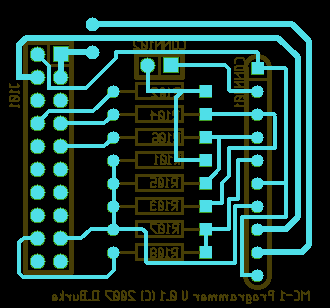
Fig-2 Pixel Map of the 'Solder' side of the MC1 Programmer board.
Having read in the Isolation File into a 'Pixel Map' the
software must then scan the Pixel Map from the bottom to the top
looking for a track to isolate.
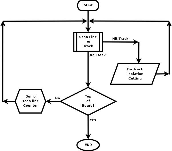
The algorithm to do this is shown next,
Fig-3 Isolation Scan Diagram
You will notice where the scan routine finds a track to isolate
( In Fig-3 the box which says 'Do Track Isolation Cutting' ).
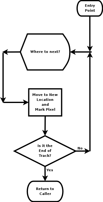
Here the scan
routine calls the automaton algorithm for each track isolation as follows,
Fig-4 Isolate Track Diagram
At
the 'Action Box' of this algorithm that says 'Move to a New Location
and Mark
pixel' there are G-code or HPGL commands written which are then
entered
into the isolation command file that is created to drive the milling
machine/plotter. The end result of all this is the scanned image shown below
which is the simulation of the isolation in Bmach2d.
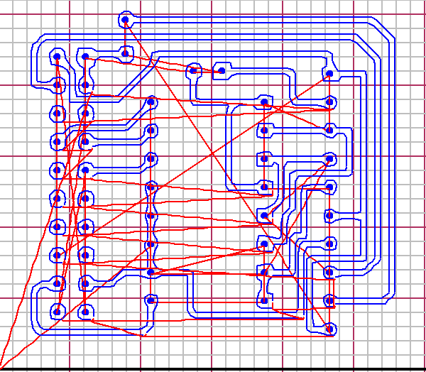 Fig-5 Programmer PCB Isolation simulation pictured in Bmach2d.
Notice the red lines in
figure-5 these are fast movement which happens once the cutter ends
cutting a track and is raised to travel to the next track. The blue
lines are the cutter or drill moving at the machining feed rate as set
by the 'F' feedrate command ( we will cover the 'TRACKS.ANC' command
file later in this demo). Compare this with the 'Overlay'
scanned from Bmach2d below which shows the isolation tool's conversion
of the Gerber file of the 'solder
side' reversed. Notice in the GCODE isolation above that each track is
cut all the way around to isolate it from other tracks on the PCB.
Pitfalls of this process are that tracks brought together to form a
closed polygon ( such as a box or triangle ) will fail because
the isolation automaton can only run around the outside of
a track edge and therefore closed polygons should be avoided. Note also
that the
isolation automaton is not able to do 'backup and retry' maneuvers so if the
isolation fails you will need to go back to the pcb layout program and
simplify the point of failure. Remember that if the isolation algorithm fails it should
fail immediately! Therefore, if there is a failure to complete an isolation look for an uncompleted track in the Bmach2d
simulation for the problem.
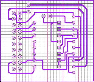 Fig-6 Programmer PCB Isolation Overlay pictured in Bmach2d.
So to begin making the PCB we will look at the following example that creates a machine command file for a milling machine.
To do this we must,
- View the Gerber files and identify which one we will use to create the isolation tracks from.
- Decide on if we are creating a plotter or milling machine command file.
- Decide whether to reverse isolate the tracks ( used for solder side isolations only! ).
- Isolate the tracks into a 'TRACK' file ('TRACKS.OVL for
the Overlay, 'TRACKS.HGL' for a plotter and 'TRACKS.ANC' for a milling
machine)
- If the 'TRACK' isolation file is for a milling machine then 'COMPILE' it into the machine command file.
- Simulate it using Bmach2d. ( Practical-2 )
- Actually cut the PCB using the 'milldrive' program or by another means e.g. send it to a plotter.
Practical 1: Create the 'TRACK' isolation file for the Printed Circuit Board,
- Open 'side4linux' and click on Project>Open Project in the Main Menue.
- double click on the 'DEMOS' Product Area,
- Double click on the 'SIDEdemos' Product,
- In
the file dialog double click the 'PCBS' folder. This takes you
to where PCB projects are kept.
- Double click on 'Mc1_programmer', this opens the 'Mc1_programmer' project folder.
- Double click on 'mc1_programmer.prf'. This opens the 'Mc1_programmer' project file.
- Notice
that the left bottom status bar window says 'Project:Mc1_programmer ' which is the
Project Name.
- Notice that the next window says 'Ptype: PCBS' which is the
Project Type.
- Click
on the 'File Explorer' 'Files' tab on the left and view what schematic
files are actually in the Project ('power').
- Click on 'Tools>PCBS>Run PCB, minimise the 'Component Library' window and maximise the main window of the 'pcb' program.
- Load the layout file 'Mc1_programmer.pcb' from the main menue of 'pcb' ('File>Load Layout').
- It should look like the graphic below,
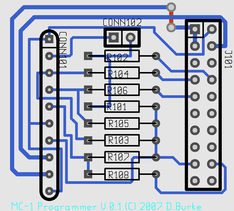 Fig-7 Screenshot of the Mc1 Programmer PCB Component Layout ( same as Fig-1 above ).
Now close the pcb' program and open the Gerber file viewer
'gerbv' from the side4linux IDE, 'Tools>PCBS>Gerber Viewer' and
click on the 'OFF' button top right.
Try clicking each button below on and off until you see the following graphic which according to the tooltip should be 'Mc1_programmer.group0.grb'.

Fig-8 Screenshot of the Mc1 Programmer PCB, 'Solder' side as seen through from the 'Component' side ( File:: Mc1_programmer.group0.grb ).
Close the Gerber viewing program and now create the reversed isolation GCODE 'TRACK.ANC' file using the tool provided as follows.
- Click on 'Tools>PCBS>Isolate GCODE Tracks Reverse'
- In the file dialog select the file to open 'Mc1_programmer.group0.grb' and click the 'Open' button.
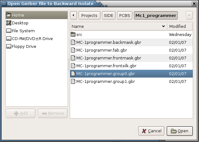
Fig-9 Screenshot of the Isolate GCODE Tracks Reverse File Dialog.
Now the final step and the one most people forget,
The procedure above has created the 'TRACKS.ANC' file and
we now need to turn this into the actual instructions that will operate
the simulator Bmach2d and the intended milling machine ( not needed if
you are creating a plotter file instead, 'Tools>PCBS>Isolate HPGL Tracks Reverse' ). So we must 'COMPILE' the 'TRACKS.ANC' file using,
'Tools>PCBS>Compile Isolation GCODE'
Do not forget to check the 'Output Window' at the bottom of the IDE to see if it compiled correctly!!
Practical-2 Simulate the milling machine isolation cutting using Bmach2d.
To simulate the milling we will open the simulator from the side4linux IDE as 'Tools>PCBS>Bmach2d
Isolation' but first let us take a look at a smaller 'TRACKS.ANC' file
to discuss it's structure as follows ( you can look at yours by
clicking the 'Open ISO FIle' button on the IDE's Toolbar and selecting
'TRACKS.ANC' to open) ,
( ===========================================================
( G-code file for 'isolation' cutting of a PCB's tracks.
( Set cutter to bottom left hand corner, just touching surface.
( Track isolation OVL file is 'TRACKS.OVL'.
(
( Use Bmach2d for visual simulation with Grid size set to 2.54mm
( for large boards or set to 1.27mm for small boards!
(
( File auto-created by side4linux,
( Check out the side4linux Project on www.sourceforge.net
( ===========================================================
@ COMPILER_ON
G90 ( absolute positioning from bottom left hand corner
G94 ( use units per minute movements
G70 ( we are using inch measurements!
F2.0 ( initial feedrate at 2 inches per minute, alter to suit!
( ========================= SUBROUTINES ========================
G57R1 ( drill hole subroutine
G0Z-0.01 ( race down to surface
G1Z0.08 ( drill hole at feed rate
G0Z-0.02 ( clear surface
G58 ( end hole drilling subroutine
(
G57R2 ( lower isolation cutter subroutine
G0Z-0.001 ( race down to surface
G1Z0.008 ( cut to bottom of isolation trench at feed rate
G58 ( end lower isolation cutter subroutine
(
G57R3 ( raise isolation cutter subroutine
G0Z-0.02 ( clear surface
G58 ( end raise isolation cutter subroutine
( ============================ MAIN ============================
( Start of program ...
(
(
(
( Start of Drill all holes ....
(
(
T#2 0.02 0 ( select 20 mil diameter twist drill for holes
( Excelon line = 'M48'
( Excelon line = 'INCH,TZ'
( Excelon line = 'T11C0.020'
( Excelon line = '%'
( Excelon line = 'T11'
( Excelon line = 'X002900Y002300'
G0X0.290000Y0.230000 ( go to start of hole
G59R1C1 ( drill a hole here
( Excelon line = 'X002900Y001300'
G0X0.290000Y0.130000 ( go to start of hole
G59R1C1 ( drill a hole here
( Excelon line = 'X002900Y003300'
G0X0.290000Y0.330000 ( go to start of hole
G59R1C1 ( drill a hole here
( Excelon line = 'M30'
( Excelon line = 'M30'
(
T#1 0.008 0 ( replace the hole drill with the isolation Tool
(
( begin track isolation cutting ....
(
G59R3C1 ( raise isolation cutter
G0X0.274000Y0.097000 ( race to start of track
G59R2C1 ( lower isolation cutter
G1X0.275000Y0.096000 ( isolation cut track
G1X0.276000Y0.096000 ( isolation cut track
G1X0.308000Y0.096000 ( isolation cut track
G59R3C1 ( raise isolation cutter
G0X0.274000Y0.197000 ( race to start of track
G59R2C1 ( lower isolation cutter
G1X0.275000Y0.196000 ( isolation cut track
G1X0.276000Y0.196000 ( isolation cut track
G1X0.308000Y0.196000 ( isolation cut track
G1X0.309000Y0.197000 ( isolation cut track
(
( End of isolation cutting so back to start condition!
(
G0Z-0.02 ( clear the surface
G0X0Y0 ( home spindle back to bottom left corner
G0Z0 ( touch the surface
M2 ( that is all!
( ============================= END ============================
From the file above we can see the CGODE instructions, one per line, the structure is,
- Preliminary comments preceded with the '(' comment out rest of line instruction
- Setup instructions such as setting the feedrate, selecting the first tool a 20mil twist drill etc.
- The Subroutine section which contains routines for hole drilling and raising/lowering the isolation engraving tool.
- The MAIN section of the program,
- where the holes are drilled,
- followed by a tool change to the isolation engraving tool,
- Isolation cutting of two tracks,
- returning to the start position,
- and finally the all important M2 end command.
You can open the Help Browser and check out the ANCA Coding Help to understand what each instruction actually does.
So now to the simulation,
With the Mc-programmer Project open, start Bmach2d 'Tools>PCBS>Bmach2d
Isolation' and set the settings for,
- Grid size of 1.27mm 'Settings>Gridsize>Gridsize 1.27'
- Set cutting speed to one quarter 'Settings>Cutting Speed divided by 4'
- Load the Overlay file 'File>Load Overlay'
- Run the Overlay file 'File>Run Overlay'
- Run the compiled 'command file' 'File>Run Cmd'
- Alter the zoom size to 2 and position using the window's slide bars 'View>Zoom>X --> 2'
If the simulation goes too quick then clear the VDU with 'View>Clear' and run it again, this time it runs slower.
In Demo-4 we will assemble the Machine Controller Programmer for the Machine Controller 'MC-1' .
We will provide other demos as 'side4linux' develops to
cover integration into a real world machine
controller.


