Demo-3    <<-BACK            HOME            UP --^           NEXT-->>  Demo-5
side4linux, a simple integrated development environment!

PCBS Demo-4  Assemble the programming PCB and programming cable for the Machine Controller.


Purpose: 
Assemble the programming PCB and programming cable for the Machine Controller.

Requirements:
Make sure that the 'GNOME' build environment is installed correctly, if not then read 'setup C build environment.txt' and also 'setup GNOME build environment.txt'.

Further Requirements: Make sure that the latest PCBS support package is installed correctly.

Pre-Requisites:

Preamble:
This is the assembly practical for the MC-1 Programmer Board, it connects between the parallel printer port of your computer and the MC-1 CPU board. It is used to program the MC-1 CPU and to verify programmed register and memory values. It also provides temporary programming power to the MC-1 CPU board via the Auxiliary Port connector. Before any assembly carefully check the PCB for broken or bridged tracks. Make sure that each pad that should not be connected is not bridged with another, this can happen if the board has been under exposed or the etching is incomplete. For the technically minded all this board does is imitate the MC-1's Auxiliary Port in programming mode. It provides pull-up and anti-ringing resistance to ensure Vin High/Low electrical specifications for AVR programming are met. Please note that although this programmer is specific to programming the MC-1 CPU it can be used to program any AVR MPU by making a small daughter board to adapt the Auxiliary Port extension lead to the pin outs that you require.


Step-1: Soldering in the resistors (either carbon or metal film, 1/4 watt rating).

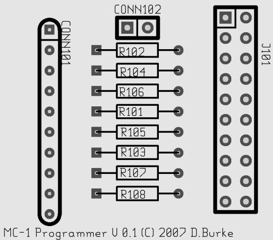
Take a look at the top view of the programmer board shown in Figure-1. You can begin assembly by soldering in the through hole 1/4 watt resistors using the following values, Make sure that the copper tracks are on the underside of the board!

Resistor Number
Resistor Value (10% tolerance)
R102
100 OHMS (100R)
R104
100 OHMS (100R)
R106
100 OHMS (100R)
R101
10 THOUSAND OHMS (10K)
R105
10 THOUSAND OHMS (10K)
R103
10 THOUSAND OHMS (10K)
R107
10 THOUSAND OHMS (10K)
R108
100 OHMS (100R)

Top view of MC-1 Programmer Board
Fig-1 MC-1 Programmer Board, Top View showing components.


Step-2: Soldering in the Connectors (IDC male).

Solder in connector 'J101' a twenty pin Insulation Displacement Ribbon Cable male header. Note that the connectors must be polarised and connected by a short ribbon cable of about eight inches in length. The IDC Ribbon Cable connects the MC-1 Programmer to the MC-1 CPU board's Auxiliary Port, these plugs face the polarisation the same way! To polarise the pin header remove Pin-1, push it into the ribbon cable plug and do the same for the other end of the cable and the MC-1 CPU ).
Connector 'CONN102' can be a two pin 'launcher' onto which you press a shorting jumper plug or you can lead it out to an external switch (recommended). It is closed during programming and open during running as the line is shared between serial port 'serial1' RXD and the 'MOSI' serial programming line (blame ATMEL for this!).


Step-3: Soldering in the Parallel Interface cable.

The programmer board is connected to your PC ( LPT:1 ) via a DB25
parallel interface cable which in the practical done here is made from a used printer cable which has had the Centronics connector removed from the other end. This is equivalant to the 'dapa' ( 'Direct AVR Parallel Access cable' ) adapter. Solder the loose ends of the cable into the holes drilled for 'CONN101' on the left hand side of the board as per the following table,

CONN101Pin Number Net Name
Printer Port Name
Parallel DB25 Pin Number OUR Colors
  Your Colors                 
1
Gnd
Ground
22 (any pin 18->25)
Blue/White

2
Mosi
Data-1 ( of 8 )
2
Brown

3
Miso
Busy
11
Pink

4
Sck
*Strobe
1
Black

5
Reset
Init
16
Orange/White


Note the color of the conductors suit our printer cable so rule out our colors and change this to suit your cable so that there is no mix up. Carefully check the connections after assembly to verify that the pin numbers match the above table exactly!


Step-4: Soldering in the Power Supply conductors.

The programmer board requires power to program the MC-1 CPU and also to supply the
MC-1 CPU serial support chips to allow for Register and Memory read routines to work. This requires you to add connections for Pins 6 -> 10 of the 'CONN101' as per the following table,

Power Net Names
CONN101 Pin Numbers
Colors
Gnd ( from power supply )
6
Black
Vcc (  plus 5 volts Regulated )
7
Red
+9V ( plus 9 Volts Regulated )
8
White
-9V ( minus 9 Volts Regulated ) 9
Yellow
Gnd ( from power supply )
10
Black


Step-5: Checking the Programming Signal conductors.

The programmer board can now be given a static check to ensure that the connections are good using a multimeter of at least 100K Ohm output impedance by comparing the input of the Parallel interface cable's DB25 Male plug to the output from the J101 connector. Place the Negative probe of the Ohmmeter ( set on a full scale resistance of 20K Ohm ) on each pin of the DB25 plug and the Positive probe on each pin of the J101 connector and test in sequence as per the following table to obtain 'Res Value-1'. Then place the negative probe on end of the power supply Vcc wire and the positive probe on pins 8,7,9,17 as per the table to get the 'Res Value-2' results. If you find something wrong then check the underside of the board for solder bridges between the connector pin pads and for breaks in the copper tracks.

DB25 Pin No. CONN101 Pin No.
J101 Pin No.
Res Value-1
Res Value-2
2
2
8
100 ohms
10.1 K
11
3
7
100 ohms 10.08 K
1
4
9
100 ohms 10.09 K
16
5
18
100 ohms 10.06 K


Step-6: Checking the Programming Power connections.

The programmer board can now be given a static check of the power supply, so connect up your power supply to the programmer board and turn it on. Be very careful when checking voltages that you only touch the probe on one pin at a time, particularly Pins 1,2,3&4 of the J101 connector. Set the voltmeter to 20 Volts with the negative probe on the common ground of your power supply ( pin 6 of 'CONN101' ) and check outputs as per the following table using the positive probe,

Connector J101 Pin Number Voltage Value
17
5 Volts Positive, do not bridge to other pins !
4
plus 9 Volts, do not bridge to Pin-1 or Pin-2 !
1 & 3
minus 9 Volts, do not bridge to Pin-2 or Pin-4 !

Well if all tests passed OK then congratulations that is the end of this practical! If all is not well then go back and check what went wrong and rectify. Remember we are using components of 5% accuracy so your results must differ slightly from ours. It is recommended that you assemble the programmer along with the power supply and programming switch ( bridging CONN-102 ) into an insulated plastic box. You could also mark on the box what it does as you will be needing it in the future for all sorts of interesting things!


In Demo-5 we will be introducing our 'guinea pig' for the 'Lathedrive1' Project, a 'Boxford 125 TCL' training computer lathe.


We will provide other demos as 'side4linux' develops to cover integration into a real world machine controller.