Demo-4    <<-BACK            HOME            UP --^           NEXT-->>  Demo-6
side4linux, a simple integrated development environment!

PCBS Demo-5 Introducing our 'guinea pig' for the 'Lathedrive1' Project, a 'Boxford 125 TCL' training computer lathe.


Purpose:  To
introduce a second hand lathe that will be used as an example of deploying the MC-1 Machine Controller.

Requirements:
Make sure that the 'GNOME' build environment is installed correctly, if not then read 'setup C build environment.txt' and also 'setup GNOME build environment.txt'.

Further Requirements:
Pre-Requisites: Read through the Overview and do Demo-1/2/3 first.

Overview:

While one can design and build a machine from scratch that would be very useful our metals manufacturing company mainly has need for recycling existing machines either purchased at low cost second hand or by adapting existing machines in our asset list that because of age are no longer supported by their manufacturer. Why would support be removed? Well many reasons, some of them are that support for the mechanical parts usually remains but because the CNC controller is sometimes outsourced to another company the manufacturer losses control of controller support. We are not blaming anyone for malpractice, the CNC contractor supplying the machine controller may simply have gone out of business or specialised parts were included in the controller design that have been withdrawn by the part manufacturer. Technology is often a two edged sword, great to have the latest hi-tech equipment but a real disaster when support for it ends. This is as it should be!! There is no place for the continued support of obsolete equipment! So the problem for us is gaining control over the %^&*$# Machine Controller! We can make any mechanical part replacement and now we will be able to design, build  and support the Machine Controller as well.

The specimen chosen for the lathe example to follow in future Demo's is a 'Boxford
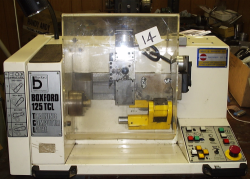
125 TCL Training Computer Lathe'  It was purchased after it was passed in at auction (LOT 14) for 350 Australian Dollars. This is a good price because it is worth $A7000 in a going condition on Ebay. The problem for the previous owner a technical college was that the lathe was given to them in a non running condition with no maintenance manuals or operating instructions. We did our own detective work but the manufacturer was not able to assist other than asking us to send the complete machine back to England from Australia ( which is on the other side of the Planet Earth ) along with a rather large sum of money. For this they would replace the electronics and upgrade the lathe to the latest specification and then ship it back to us some time much later into the future. As you can see from the following photo the lathe is small ( which is good as we would not like a large one to run amok while developing the Machine Controller software!! ), and in very good mechanical condition as it has hardly ever been used!

Boxford lathe as purchased
Fig-1 Boxford 125TCL Training Computer Lathe as purchased for $A350 - Front View.

The lathe is very clean having done very little work but notice the control panel on the lower right, this is not on the later models as it can get very dirty from coolant splash and metal debris from the workpiece. Notice that this is a 'proper' industrial CNC lathe with the bed up on the vertical plane so that turnings can fall away from the tool and workpiece, very nice!
Boxford lathe rear view
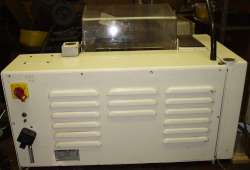
Fig-2 Boxford 125TCL Training Computer Lathe as purchased for $A350 - Rear view.
Boxford lathe after electronics are removed

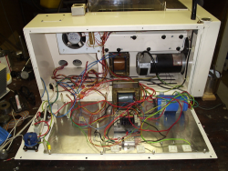
Fig-3 Boxford 125TCL Training Computer Lathe after failed electronics have been removed.

From the top left you can see the cooling fan. In the middle top is the DC motor smoothing choke and top right is the DC spindle motor that provides a variable speed drive to the lathe's three jaw chuck. Bottom left is the main power isolator, fuses and overload circuit breaker. In the middle bottom is the control circuit power supply consisting of a 24 volt transformer, a bridge rectifier and to the bottom right is the control power supply smoothing capacitor that removes any ripple from the raw DC output.

Boxford lathe bits thrown out
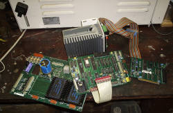
Fig-4 Boxford 125TCL Training Computer Lathe showing failed electronics that were removed.

From Figure-4 you can see from the left the axis power board which is burnt out. In the middle is the Zilog Z80 based machine controller. At the right end is the ISA bus communication card that slots into a PC to connect the PC to the lathe along with it's 50 conductor IDC ribbon cable. In the middle top with the finned alluminium extrusion is the variable speed drive module that supplies the 150 volt DC spindle motor.

Some Basics:
 
Boxford axis closup
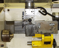
Fig-5 Boxford 125TCL Training Computer Lathe showing tool axis and main spindle.

Figure-5 is a closeup of the main bed in the vertical plane with the tool slide holding a single position tool holder in which is clamped a parting off tool. Notice the three jaw chuck at the left currently holding a piece of brass rod. The yellow section is a drop down tail stock used for turning between centers. You can see the two stepping motors that drive the X and Z axis slides, these are connected to their feed screws using rubber toothed belts which is current practice. Notice the two axis arrows showing axis name and directional polarity ( 'X' & 'Z' ). In all G-code programming the spindle is the 'Z' axis and although the slides actually do the moving while the spindle stays still G-code actually treats it the other way around. Therefore if the spindle 'moves' toward the work tool that is a Z axis positive move and away is a Z axis negative move. Also on this lathe X axis positive is towards the tool, that is the spindle is imagined to move towards the tool. Hence any imagined movement of the spindle towards the tool on this lathe is positive.


Collecting the needed Information:

We need the following for a basic installation of our Machine Controller,
  1. The type of axis drive (stepping motors in this case)
  2. The distance each slide moves per step of the drive stepping motor.
  3. The axis deadband or 'drive slack' (the number of steps after an axis reversal until the slide moves again).
  4. The type of spindle drive.
Boxford determine axis movement per step
Fig-6 Boxford 125TCL Training Computer Lathe determining axis movement per step of stepping motor using a dial gage.

Each axis slide movement is controlled on this lathe with a 24volt four phase bi-polar (axis drives will be explained in later Demo's) stepping motor and was determined to be 0.4 thousands of an inch for the X axis (25 steps in 10 thou of the dial gage)  with about 8 steps of axis dead band. The Z axis was about the same. Note we will fine tune these values after machining some metal so that the theoretical can meet the real world. The spindle drive was determined to be a 150 volt direct current motor driving through a 'V' belt to the work spindle. This was figured out after cleaning and reading information from nameplates on the motor and the original spindle drive electronic module. We are now ready to proceed with the conversion to the new Machine Controller. Please note that depending on the machine this demo may need to be read with a 'grain of salt' as different machines have different setups however the current machine Controller is designed to power stepper motor driven axis slides so the information obtained is correct in this particular example.


In Demo-6 we will Introduce the 'MC-1' Machine Controller Central Processing Unit.


We will provide other demos as 'side4linux' develops to cover integration into a real world machine controller.