Fig-1 Pin out diagram for the Atmel AVR Mega 128 (C) Atmel.
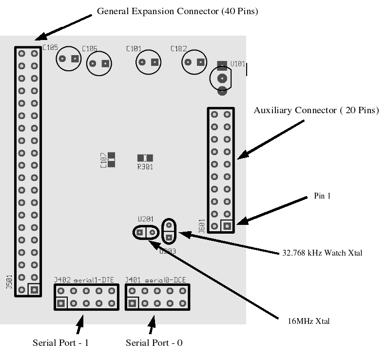
Figure-2 below shows the layout
of the MC-1 CPU with ports marked,

Fig-2 MC-1 CPU Layout.
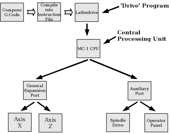
Figure-3 shows the relationship
between the higher level Tools provided with side4linux
and the MC-1 Central Processing Unit. Once a G-Code file has been
compiled by the Production Manager it can be passed from the
controlling Linux PC using one of the 'Drive' programs ( Lathedrive in
this lathe example) to the MC-1 CPU which is then under the Machine
Operator's control. The Machine Operator will program
the number of parts needed and feed the machine with metal rod as
required. As you can see there are two points of control. Firstly the
Lathedrive program must be activated to feed the raw step commands to
the MC-1 and secondly, the Operator can use the Operator
Panel on the Lathe to start, stop, change tooling and make dimensional
adjustments.

Fig-3 Machine Controller Overview.
On the MC-1 CPU board are also MC1488 line driver and MC1489 line receiver chips to drive the serial ports needed for communicating with the controlling PC and another 'slave' if required. To complete the Machine Controller you need to add an Axis Power Board and a Spindle Drive Board, examples of which will be found in later Demo's.
For a more technical explanation of the MC-1 please review the current MC-1 Operating Manual (Local)