Demo-6    <<-BACK            HOME            UP --^           NEXT-->>  Demo-8
side4linux, a simple integrated development environment!

PCBS Demo-7  Assemble the programming PCB and programming cable for the Machine Controller.


Purpose: 
Assemble  the Machine Controller MC-1 Central Processing Unit.

Requirements:
Make sure that the latest help packages are installed.

Further Requirements:
Pre-Requisites: Read through the Overview and do Demo-1/2/3/4/5/6 first.
Preamble:
This is the assembly practical for the MC-1 CPU Board, it connects between the parallel printer port of your computer, the Axis board and the Auxiliary board. The board can be produced using the PCBS support package or you can send the Gerber and Drill files provided in the 'PRODUCTS/MC1/PCBS/Mc1' directory straight to a PCB manufacturer.


Step-1: Soldering in the wire links.

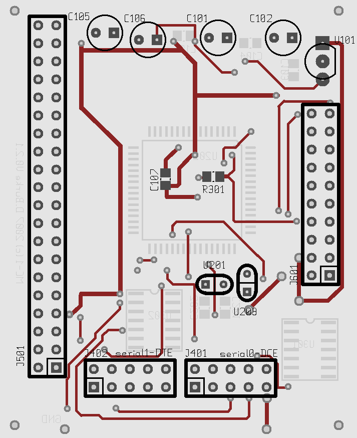
We recommend that the pcb be made by a professional board maker using plated through hole, two sided technology with solder masks. However if you are doing a single sided home made board then you will need to solder in the links in Figure-1 below. This is the Solder side of the board, the Component side holds all of the surface mount chips which will be added later (shown grayed out). Make sure that the link connections added under the Atmel AVR Mega 128 are of low profile. You may need to bend the AVR's legs down a bit to increase clearance but do not over do this! Stick the links down with PVA or cyanoacrylate glue or use sticky tape to prevent them moving around. To ensure that the solder blobs from the wire links are of low profile you may file them to half thickness using a mill saw file. Now brush clean the board using a one inch flat paint brush dipped in turpentine, this removes the metal fillings embedded into the residual solder flux. Finnish by wiping the excess turpentine off with a clean cotton rag and allow to dry. Do the cleaning outdoors to avoid breathing in the turpentine vapor,  keep it away from your skin and clothing as well. You can add in the surface mount (SMD) resistor R301 here, it is approx 2k Ohms ( 1k -> 4k7 ). When completed re-tin all of the SMD pads particularly the AVR Mega128 pads and leave the flux residue on the board ( more flux is better than less! ).

Top view showing links
Fig-1 MC-1 CPU Board, Top View showing Solder Side components and solder links.


Step-2: Testing the power.
Solder in the J601 Auxiliary Port connector, a polarised male IDC ribbon cable male socket.
As this connector is polarised (polarisation cut out to the right with the board facing up as per figure-1) please first make sure that you are soldering it in the correct way around! This connector must be pin for pin compatible with the MC-1 Programmer board made earlier in Demo-4. The programmer board is now connected to the CPU board via the six inch long IDC ribbon cable that was made as part of Demo-4 and powered up. Make sure that you attach the ground fly lead from the Programmer to the ground pad in any corner of the MC-1 CPU.

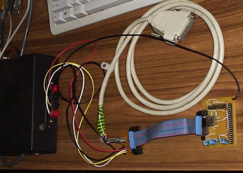
Overview of Power Supply, Adapter, CPU
Fig-2 Overview of Power Supply, Programming Adapter and MC-1 CPU with the DB25 Programming cable.


Now with the aid of a multimeter test the following voltages with the positive probe, the negative probe should be attached to the negative of the power supply.

Location
Voltage Expected (approx.)
IC U301 Pin 1
minus nine volts
IC U301 Pin 14 plus nine volts
IC U302 Pin 14
plus five volts
IC U202 Pin 64
plus five volts
IC U202 Pin 62  zero volts
IC U202 Pin 52
plus five volts
IC U202 Pin 22
plus five volts
IC U202 Pin 52
zero volts


Step-3: Soldering in the capacitors and inductor.

Take a look at the top view of the CPU board shown in Figure-1. With the board powered down solder in the three through hole electrolytic capacitors C101, C102, C105 on the solder side of the board (opposite from the AVR MPU chip). Note that the square terminal is the positive end of the circuit. The values are not critical perhaps between 2 and 33 micro Farads would be sufficient but insure that you respect the voltage polarity!. Solder in the ceramic disc capacitor C106 of 100nF.  Now power up the board again using the MC-1 Programmer and check voltages again to detect any faults, beware eletrolytics must never be connected wrongly because they may catch fire or even explode!


Step-4: Soldering in the Regulator IC, other active components and the Connectors (IDC male sockets).

Step-5: Soldering in the Passive chips.

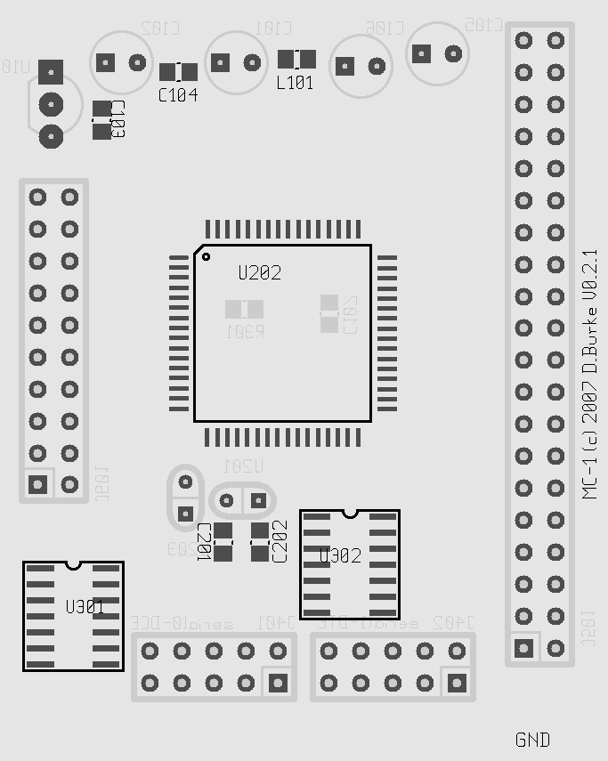
Make sure the board is powered down and turn the CPU board over. View Figure-3 below and locate the positions for C201, C202, C103 and C104. Note the capacitors are ceramic, non- polarised. Should you not have SMD components available here then use leaded ones with the leads suitably bent and stand them upright to fit. Lightly tin the connection pads with solder and solder in the components with the values shown in the table below,

MC-1 Top Components
Fig-3 MC-1 CPU Board, Bottom View showing Component Side SMD components.

Passive SMD Chips
Name
Value
L101 Nominal, say 10 uH approx
C103
Nominal, say 0.05 to 0.1 uF approx ceramic
C104
Nominal, say 0.05 to 0.1 uF approx ceramic
C201
Nominal, say 20 pF approx ceramic depending on the crystal used
C202
Nominal, say 20 pF approx ceramic depending on the crystal used
C107
Nominal, say 0.05 to 0.1 uF approx ceramic

Power up the board again and re-check the voltages as per Step-2, notice that IC U202 Pin 62 ( Analog reference voltage from the regulator U101 ) should now be five volts. switch off the power ready for Step-6.


Step-6: Soldering in the SMD Serial chips.

Make sure the CPU board is powered down. Before beginning make sure you understand safe anti-static procedures for CMOS chips such as the use of a grounded wrist strap, grounded work surface and grounded anti-static tools etc. Make sure that you have a good understanding about which pin is Pin-1 on each chip and the correct orientation required for each location on the board. For the Serial SMD chips they should face up and Pin-1 is left top. View Figure-3 above and locate the positions for U301 a MC1488 Serial Line Driver chip. Very lightly tin the connection pads with solder and solder in the component. Do the same for U302 a MC1489 Serial Line Receiver chip. Then using a 10 times lighted microscope check for any solder bridges between pads, use solder wick braid if necessary to reduce the amount of solder so that surface tension pulls the bridging apart.

As a tip to new comers SMD devices can be soldered in using the 'wave soldering process', that is,
  1. Tack down the pins in each corner of the chip to the pre-tinned pads using the soldering iron and visually check for perfect alignment.
  2. Using plenty of solder and plenty of flux, run a ball of solder up and down one side of the chip's legs.
  3. Using a grounded solder sucker heat up and remove the blob from the corner of the chip where you stopped.
  4. Repeat the wave soldering for the other side/sides of the chip.
  5. Soak up any excess solder using solder wick (pre-fluxed copper braid) heated from above by the iron.
  6. Visually check for solder bridging between legs using a lighted microscope of at least magnification ten.
An alternative method of soldering a SMD device is the 'spot welder technique'. This starts with the tacking down of the chip as per the 'wave soldering' process already described over a tinned set of pads but instead of flowing solder over the top we just press the tip of the soldering iron onto the top of each leg and push it into the pad solder below. This process takes about two seconds per pad and is the least messy process to use. Make sure if you use this method to check the continuity of the connection as no additional solder or flux is being added to help 'wet' the joint.

To remove a SMD chip use the 'fuse wire technique' that is,
  1. Tack down a length of fine fuse wire at one end under and diagonally opposite the starting leg.
  2. Slide the wire under the starting leg and gently heat the leg from the top using the tip of the soldering iron.
  3. Prise the leg far enough off the board with the wire to break the solder connection to the pad.
  4. Repeat till the one leg is left attached to the board and the wire.
  5. Remove the last leg and the fuse wire from the board with the soldering iron and tweezers.
Of course if you have professional equipment available then disregard our instructions and use it instead as per the suppliers directions!
At this point we would recommend that you jump to Step-8 and do the 'Smoke Test' before doing Step-7, but that is your call.


Step-7: Soldering in the Atmel AVR ATMega128 chip.

Make sure the board is powered down. View Figure-3 above and locate the position for U202 an Atmel AVR Mega-128 MPU chip. Very lightly tin the connection pads with solder and solder in the chip but noting the position of the chamfer on one corner which must be oriented correctly as the chip has the same number of pins on all sides making any other form of visual identification difficult. If you feel that your board is now complete then do Step-8, if not then revise the Practical from the start to ensure that you have not missed anything.


Step-8: Smoke Test!

Check thoroughly that you have assembled all of the components onto the board correctly. Now very briefly power up the board with the programming adapter and then feel for any heat from components. Power up for a longer time and do some voltage checks but be sure not to bridge across any IC leg or other track, this could create a short circuit and ruin all your good work! Always remember that smoke is very expensive! If you let some smoke escape then you may need to remove some of the chips and go back and do the Practical again!

Well if all tests passed OK then congratulations that is the end of this practical! If all is not well then go back and check what went wrong and rectify. Remember we are using components of 5% accuracy so your results must differ slightly from ours which will be quite acceptable. You now need to put the
MC-1 CPU away to await Demo-8 where we will test it to see if it is working. Remember to use CMOS static electricity handling procedures from now on for your new MC-1 CPU, just as you would for any other electronic boards.


In Demo-8 we will Program the 'MC1' Machine Controller with the AVR assembly code 'Debug' monitor.


We will provide other demos as 'side4linux' develops to cover integration into a real world machine controller.