Step-1: Test the MC-1 Programmer.
As a first step in the Practical we are going to test the signal lines from your computer through the Programmer, but first please test with a multimeter and ensure that there are no short circuits between lines ( zero Ohms ). Connect up the Power Supply to the Programmer ( and nothing else! ) and switch on. Check all your voltages are correct and switch off. Now plug in the cable to connect the parallel printer port of your computer to the Programmer and switch on. Your computer should be still operating normally! Bring up the side4linux IDE on your computer and open the test project's 'hello.prf' file, /SIDE/PRODUCTS/MC1/AVRA/Hello/hello.prf using 'Project>Open Project' from the Main Menu as follows,
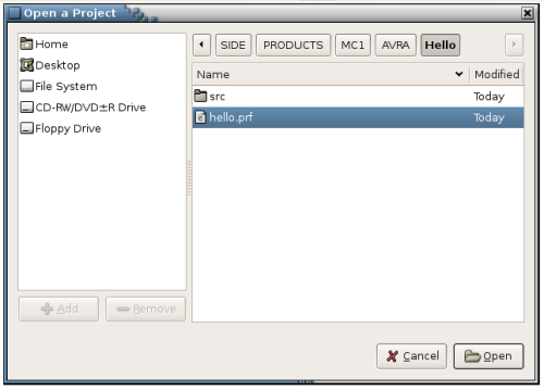
Fig-1 Open Hello Project Dialog
Now open the file 'hello.asm' using the 'Open-TXT' Toolbar button. You are now looking at a basic master assembly file for the Machine Controller modified for the 'Hello World' practical in Demo-9 to follow. Click on the 'Build' button in the Toolbar and you should see the following in the Output Window below the open file.
You have done more than just assemble the code, the IDE has also transferred your machine code program Flash file and your EEprom data file to the 'dbavrprog' serial programming program's 'files' directory ready for uploading to your MC-1 CPU. These files are 'upprog.hex' and 'upeeprom.hex',
in 'Intel 8-bit Hex' file format. Note that if you were building your own board for an unrelated Product then the procedure will remain the same but we are concentrating only on the MC-1 for the rest of this Demo. OK, now that you have code to upload to your MC-1 CPU you will need to open the 'dbavrprog' program to program your AVR chip but first a discussion about access 'permissions'.
On Linux users can have their power to access the hardware and/or programs on a computer increased to unlimited use or just restricted to a very small area! This process is called 'setting the permission level' for that user. The Systems Administrator can make someone the 'Super User' 'root' who has unlimited access such as the SA but more likely the SA will limit access via a program such as 'sudo'. The 'sudo' program is not part of side4linux but comes with all Linux Distributions as a helper program. This program allows privileged users access to specified hardware and programs as if they were the 'Super User' but no access to anything else. OK, so you are just a hobbyist running Ubuntu on your own home computer, you will need just to enter your log in password when asked and you will be off. So why the fuss? In a bigger organisation with many computers and CNC ( read dangerous automatic ) machinery it matters a great deal who can have access. A designer may well have access to the programming program that your are about to use but may have no access to the 'drive programs' such as 'Lathedrive' or 'Milldrive' etc. that actually controls CNC equipment. Novice apprentices are a good example of workers who must be supervised at all times by a qualified trades person. This is industrial law in Australia and in many other countries and is usually referred to as 'employee/employer mutual obligation under Occupational, Health, Welfare, Safety and Environmental regulations'.
So in short side4linux programs that access the hardware on your computer are called via the 'sudo' program as 'sudo theCalledProgram optionsList'.
So how are the user permissions set? Permissions are set by entering them into a special text file on the computer called 'sudoers'.
As an exercise look for yours using the 'whereis' command from a terminal e.g.
So I have two options /etc/sudoers and /usr/share/man/man5/sudoers.5.gz
this
means I could issue the 'info sudoers'
command from the terminal for
the information on sudoers or I could edit the sudoers file '/etc/sudoers' from a
super user's terminal as say 'gedit
/etc/sudoers'.
The contents of the 'sudoers' file on the office PC which I share is as follows,
Look at the area under the line, '# User privilege specification', this 'sudoers' file gives the super user 'root' full privileges and also any one in the 'admin' group full access also. The last line of the file says that those in the 'db' users group namely me (David Burke) can have super user access to the ports needed by the 'dbavrprog' program. So if you are just an ordinary user of this computer like me you need to be in the 'db' group. If you are the only user such as our hobbyist on Ubuntu mentioned earlier then you would be in the 'admin' group by default and hence covered by all sudo launched programs.
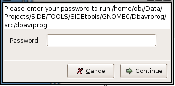
So after all that let use launch the serial programming program as 'Tools>AVRA>AVR PROGRAM', you should be greeted by 'sudo's' password dialog similar to the graphic below,
As a first step in the Practical we are going to test the signal lines from your computer through the Programmer, but first please test with a multimeter and ensure that there are no short circuits between lines ( zero Ohms ). Connect up the Power Supply to the Programmer ( and nothing else! ) and switch on. Check all your voltages are correct and switch off. Now plug in the cable to connect the parallel printer port of your computer to the Programmer and switch on. Your computer should be still operating normally! Bring up the side4linux IDE on your computer and open the test project's 'hello.prf' file, /SIDE/PRODUCTS/MC1/AVRA/Hello/hello.prf using 'Project>Open Project' from the Main Menu as follows,

Fig-1 Open Hello Project Dialog
Now open the file 'hello.asm' using the 'Open-TXT' Toolbar button. You are now looking at a basic master assembly file for the Machine Controller modified for the 'Hello World' practical in Demo-9 to follow. Click on the 'Build' button in the Toolbar and you should see the following in the Output Window below the open file.
Removing
src/hello.hex
Removing src/hello.eep.hex
Building src/hello
AVRA: advanced AVR macro assembler Version 1.2.0 Build 30 (15. October 2006)
Copyright (C) 1998-2006. Check out README file for more info
AVRA is an open source assembler for Atmel AVR microcontroller family
It can be used as a replacement of 'AVRASM32.EXE' the original assembler
shipped with AVR Studio. We do not guarantee full compatibility for avra.
AVRA comes with NO WARRANTY, to the extent permitted by law.
You may redistribute copies of avra under the terms
of the GNU General Public License.
For more information about these matters, see the files named COPYING.
Pass 1...
Pass 2...
done
Assembly complete with no errors.
Segment usage:
Code : 604 words (1208 bytes)
Data : 0 bytes
EEPROM : 28 bytes
Removed upload hex program Flash file from dbavrprog
Removed upload hex data EEprom file from dbavrprog
Copying Flash and EEprom hex files to dbavrprog
You have done more than just assemble the code, the IDE has also transferred your machine code program Flash file and your EEprom data file to the 'dbavrprog' serial programming program's 'files' directory ready for uploading to your MC-1 CPU. These files are 'upprog.hex' and 'upeeprom.hex',
in 'Intel 8-bit Hex' file format. Note that if you were building your own board for an unrelated Product then the procedure will remain the same but we are concentrating only on the MC-1 for the rest of this Demo. OK, now that you have code to upload to your MC-1 CPU you will need to open the 'dbavrprog' program to program your AVR chip but first a discussion about access 'permissions'.
On Linux users can have their power to access the hardware and/or programs on a computer increased to unlimited use or just restricted to a very small area! This process is called 'setting the permission level' for that user. The Systems Administrator can make someone the 'Super User' 'root' who has unlimited access such as the SA but more likely the SA will limit access via a program such as 'sudo'. The 'sudo' program is not part of side4linux but comes with all Linux Distributions as a helper program. This program allows privileged users access to specified hardware and programs as if they were the 'Super User' but no access to anything else. OK, so you are just a hobbyist running Ubuntu on your own home computer, you will need just to enter your log in password when asked and you will be off. So why the fuss? In a bigger organisation with many computers and CNC ( read dangerous automatic ) machinery it matters a great deal who can have access. A designer may well have access to the programming program that your are about to use but may have no access to the 'drive programs' such as 'Lathedrive' or 'Milldrive' etc. that actually controls CNC equipment. Novice apprentices are a good example of workers who must be supervised at all times by a qualified trades person. This is industrial law in Australia and in many other countries and is usually referred to as 'employee/employer mutual obligation under Occupational, Health, Welfare, Safety and Environmental regulations'.
So in short side4linux programs that access the hardware on your computer are called via the 'sudo' program as 'sudo theCalledProgram optionsList'.
So how are the user permissions set? Permissions are set by entering them into a special text file on the computer called 'sudoers'.
As an exercise look for yours using the 'whereis' command from a terminal e.g.
db@wks1:~$
whereis sudoers
sudoers: /etc/sudoers /usr/share/man/man5/sudoers.5.gz
db@wks1:~$
sudoers: /etc/sudoers /usr/share/man/man5/sudoers.5.gz
db@wks1:~$
The contents of the 'sudoers' file on the office PC which I share is as follows,
# /etc/sudoers
#
# This file can be edited with the 'gedit /etc/sudoers' command as root.
#
# See the man page for details on how to write a sudoers file.
#
# Host alias specification
# User alias specification
# Cmnd alias specification
# Defaults
Defaults !lecture,tty_tickets,!fqdn
# User privilege specification
root ALL=(ALL) ALL
# Members of the admin group may gain root privileges
%admin ALL=(ALL) ALL
# add to allow use of dbavrprog program for members of group 'db'
%db ALL = /home/db/Data/Projects/SIDE/TOOLS/SIDEtools/GNOMEC/Dbavrprog/src/dbavrprog
#
# This file can be edited with the 'gedit /etc/sudoers' command as root.
#
# See the man page for details on how to write a sudoers file.
#
# Host alias specification
# User alias specification
# Cmnd alias specification
# Defaults
Defaults !lecture,tty_tickets,!fqdn
# User privilege specification
root ALL=(ALL) ALL
# Members of the admin group may gain root privileges
%admin ALL=(ALL) ALL
# add to allow use of dbavrprog program for members of group 'db'
%db ALL = /home/db/Data/Projects/SIDE/TOOLS/SIDEtools/GNOMEC/Dbavrprog/src/dbavrprog
Look at the area under the line, '# User privilege specification', this 'sudoers' file gives the super user 'root' full privileges and also any one in the 'admin' group full access also. The last line of the file says that those in the 'db' users group namely me (David Burke) can have super user access to the ports needed by the 'dbavrprog' program. So if you are just an ordinary user of this computer like me you need to be in the 'db' group. If you are the only user such as our hobbyist on Ubuntu mentioned earlier then you would be in the 'admin' group by default and hence covered by all sudo launched programs.
So after all that let use launch the serial programming program as 'Tools>AVRA>AVR PROGRAM', you should be greeted by 'sudo's' password dialog similar to the graphic below,

Fig-2 Sudo Dialog Box.
After
using your normal password that you signed on with and on clicking the
Continue' button you should now have the dbavrprog screen up on your
display as follows,
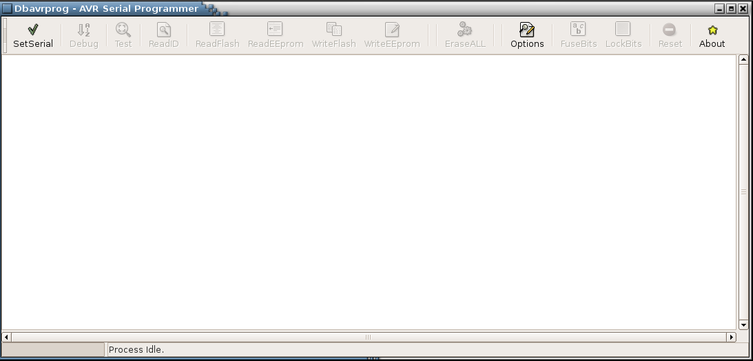
Fig-3 dbavrprog sign on screen.
Now to set up access to your printer port, click on the 'SetSerial' button and you should be greeted with the message,
Step-2: Testing the power.
Notice that most of the other Toolbar buttons should no longer be grayed out. You can now plug in and switch on your programmer. We can try toggling the serial switching lines, 'RESET', 'MOSI' and 'SCK'.
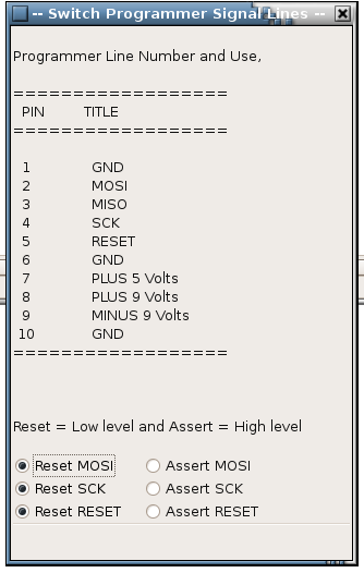
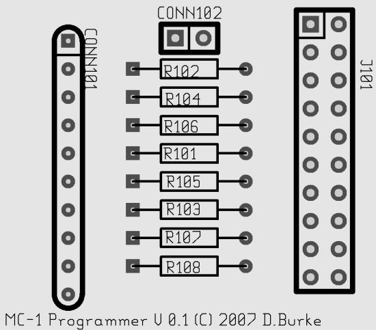
Click on the 'Debug' Toolbar button and look at the following graphics in Figures-4/5,

Fig-3 dbavrprog sign on screen.
Now to set up access to your printer port, click on the 'SetSerial' button and you should be greeted with the message,
I/O
Permission granted
Port Access Granted, you may continue!
Port Access Granted, you may continue!
Step-2: Testing the power.
Notice that most of the other Toolbar buttons should no longer be grayed out. You can now plug in and switch on your programmer. We can try toggling the serial switching lines, 'RESET', 'MOSI' and 'SCK'.
Click on the 'Debug' Toolbar button and look at the following graphics in Figures-4/5,
 |
 |
| Fig-4 Debug Dialog |
Fig-5 Programmer Top View |
You need to place a logic probe on each
signal line at 'CONN101'
corresponding with the signal to be toggled then click on the radio
buttons in the Debug Dialog. The logic probe should go from low to high
and back as you click from one radio button and back (use a multimeter
set to twenty volts if you do not have a logic probe in which case low
= 0 volts and high = 5 volts approx.). If your lines seem stuck high or
low or the other voltages do not tally then switch off and disconnect
the programmer and check for shorting between the pads and wiring. Once
you are past this point close down the 'dbavrprog'
program and switch
off. Connect the MC-1 CPU ready for programming by plugging in the
ribbon cable, make sure the switch across 'CONN102'
is closed! Notice that you bring up the programmer program and click on
the 'SetSerial' button before
powering up the power supply, use this
sequence always!
