Step-1: Build the Hello Project and load it
into the MC-1 CPU using the MC-1 Programmer.
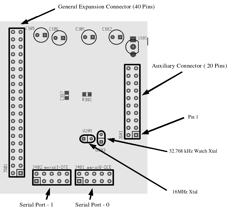
As a first step in the Practical we are going to connect up all the cables used in Practical-8 and switch the computer on and then switch the power supply on. Check all your voltages are correct and switch off in reverse sequence. Now plug in the Serial cable from 'Serial Port-0' of the MC-1 CPU to an RS232C Serial Port of your computer (refer to Figure-0 below for the correct position for 'Serial-0'). Notice here that Serial-1 shares the PortE pins with the Programmer (Atmel did this not us!) so make sure always that Serial-1 has no cable plugged into it during programming on any occasion! You should have removed the pin from pin-1 (the square sided one ) of the male IDC ribbon cable socket and pushed it into the 10 pin female plug of the serial communication ribbon cable. By doing this first you are polarizing the plug and socket so that they cannot be plugged together the wrong way round. Do not be tempted to use polarized 10 pin sockets on the pcb as we will use a 22 ribbon cable plug when needing to use both serial communication ports.

Fig-0 MC-1 CPU Top Layout showing Serial Port - 0
Switch on your computer once the serial communication ribbon cable is plugged in. Your computer should be still operating normally!
Set your preferences to the Serial port you have used, either '0' for the first serial port or '1' for the second
with 'Preferences>IDE>Basic>ComPort'
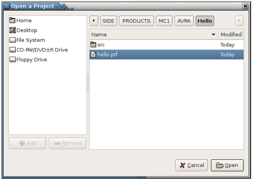
Bring up the side4linux IDE on your computer and open the test project's 'hello.prf' file, /SIDE/PRODUCTS/MC1/AVRA/Hello/hello.prf using 'Project>Open Project' from the Main Menu as follows,

Fig-1 Open Hello Project Dialog
Now open the file 'hello.asm' using the 'Open-TXT' Toolbar button. You are now looking at a basic master assembly file for the Machine Controller modified for the 'Hello World' practical in this Demo. Click on the 'Build' button in the Toolbar and you should see the following in the Output Window below the open file.
You have done more than just assemble the code, the IDE has also transferred your machine code program Flash file and your EEprom data file to the 'dbavrprog' serial programming program's 'files' directory ready for uploading to your MC-1 CPU. These files are 'upprog.hex' and 'upeeprom.hex', in 'Intel 8-bit Hex' file format. Note that if you were building your own board for an unrelated Product then the procedure will remain the same but we are concentrating only on the MC-1 for the rest of this Demo. OK, now that you have code to upload to your MC-1 CPU you will need to open the 'dbavrprog' program to program your AVR chip '. Launch the serial programming program as 'Tools>AVRA>AVR PROGRAM', you should be greeted by 'sudo's' password dialog similar to the graphic below,

As a first step in the Practical we are going to connect up all the cables used in Practical-8 and switch the computer on and then switch the power supply on. Check all your voltages are correct and switch off in reverse sequence. Now plug in the Serial cable from 'Serial Port-0' of the MC-1 CPU to an RS232C Serial Port of your computer (refer to Figure-0 below for the correct position for 'Serial-0'). Notice here that Serial-1 shares the PortE pins with the Programmer (Atmel did this not us!) so make sure always that Serial-1 has no cable plugged into it during programming on any occasion! You should have removed the pin from pin-1 (the square sided one ) of the male IDC ribbon cable socket and pushed it into the 10 pin female plug of the serial communication ribbon cable. By doing this first you are polarizing the plug and socket so that they cannot be plugged together the wrong way round. Do not be tempted to use polarized 10 pin sockets on the pcb as we will use a 22 ribbon cable plug when needing to use both serial communication ports.

Fig-0 MC-1 CPU Top Layout showing Serial Port - 0
Switch on your computer once the serial communication ribbon cable is plugged in. Your computer should be still operating normally!
Set your preferences to the Serial port you have used, either '0' for the first serial port or '1' for the second
with 'Preferences>IDE>Basic>ComPort'
Bring up the side4linux IDE on your computer and open the test project's 'hello.prf' file, /SIDE/PRODUCTS/MC1/AVRA/Hello/hello.prf using 'Project>Open Project' from the Main Menu as follows,

Fig-1 Open Hello Project Dialog
Now open the file 'hello.asm' using the 'Open-TXT' Toolbar button. You are now looking at a basic master assembly file for the Machine Controller modified for the 'Hello World' practical in this Demo. Click on the 'Build' button in the Toolbar and you should see the following in the Output Window below the open file.
Removing
src/hello.hex
Removing src/hello.eep.hex
Building src/hello
AVRA: advanced AVR macro assembler Version 1.2.0 Build 30 (15. October 2006)
Copyright (C) 1998-2006. Check out README file for more info
AVRA is an open source assembler for Atmel AVR microcontroller family
It can be used as a replacement of 'AVRASM32.EXE' the original assembler
shipped with AVR Studio. We do not guarantee full compatibility for avra.
AVRA comes with NO WARRANTY, to the extent permitted by law.
You may redistribute copies of avra under the terms
of the GNU General Public License.
For more information about these matters, see the files named COPYING.
Pass 1...
Pass 2...
done
Assembly complete with no errors.
Segment usage:
Code : 604 words (1208 bytes)
Data : 0 bytes
EEPROM : 28 bytes
Removed upload hex program Flash file from dbavrprog
Removed upload hex data EEprom file from dbavrprog
Copying Flash and EEprom hex files to dbavrprog
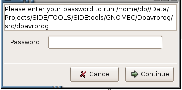
You have done more than just assemble the code, the IDE has also transferred your machine code program Flash file and your EEprom data file to the 'dbavrprog' serial programming program's 'files' directory ready for uploading to your MC-1 CPU. These files are 'upprog.hex' and 'upeeprom.hex', in 'Intel 8-bit Hex' file format. Note that if you were building your own board for an unrelated Product then the procedure will remain the same but we are concentrating only on the MC-1 for the rest of this Demo. OK, now that you have code to upload to your MC-1 CPU you will need to open the 'dbavrprog' program to program your AVR chip '. Launch the serial programming program as 'Tools>AVRA>AVR PROGRAM', you should be greeted by 'sudo's' password dialog similar to the graphic below,

Fig-2 Sudo Dialog Box.
After
using your normal password that you signed on with and on clicking the
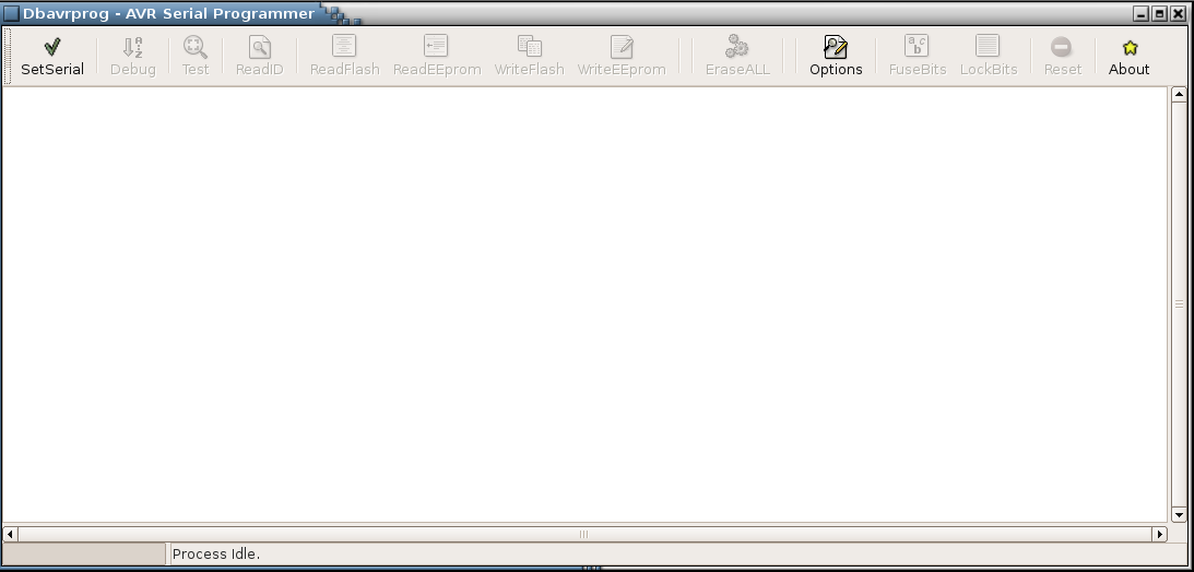
Continue' button you should now have the dbavrprog screen up on your
display as follows,

Fig-3 dbavrprog sign on screen.
Now to set up access to your printer port, click on the 'SetSerial' button and you should be greeted with the message,

Fig-3 dbavrprog sign on screen.
Now to set up access to your printer port, click on the 'SetSerial' button and you should be greeted with the message,
I/O
Permission granted
Port Access Granted, you may continue!
Port Access Granted, you may continue!